
Squeeze Pins
With the increasing complexity of castings, shrinkage porosity due to poor feeding is often inevitable in large part sections, despite optimized gating and feeding systems and proper die temperature management. In high pressure and permanent mold castings, squeeze pins are frequently used to locally press the metal to reduce shrinkage porosity. However, the effectiveness of squeeze pins is highly dependent on their placement and on the timing of pressurization. In order to predict these real-world scenarios, a squeeze pin model has been developed in FLOW-3D CAST to help design and optimize the squeeze pin process parameters.
Squeeze Pin Model
The squeeze pin model is based on the prescribed-motion moving objects model and works with the simple shrinkage model based on heat transfer and solidification dynamics considerations. Once activated, a squeeze pin senses the amount of shrinkage in the adjacent liquid metal and moves in to exactly compensate for that volume. The squeeze pin stops if it runs the maximum allowed distance or encounters too much solidified metal on its surface. A force can be defined for a pin and is translated into metal pressure. That pressure can then be used together with the thermal stress evolution and micro-porosity models.
The timing of a squeeze pin’s activation is a component of the model. The model provides several flexible activation controls. A squeeze pin can be activated at a user-prescribed time, by an Active Simulation Control event or it can be set to activate automatically. In the latter case, the squeeze pin is activated if the following conditions are met:
- the pin is adjacent to a liquid region,
- the pin is not connected to another pin via a contiguous liquid path to avoid competition between pins, and
- the adjacent liquid region does not have a free surface where metal could be pushed out of the cavity before the gate is sealed by the solidified metal.
The automatic activation control is useful during the design stage, when the exact timing of a pin is not known. In that case, the pin activation time is a part of the model output.
Active Simulation Control can be used to mimic the real squeeze pin control system on a die casting machine. It allows the user to add more control and refinement to the pin timing, based on the solution in different parts of the casting.
Squeeze Pin Model Applications
- Simulate the effect of squeeze pins in reducing or eliminating porosity in hard-to-feed areas of the casting
- The shot sleeve piston can be defined as a squeeze pin during solidification to compensate for solidification shrinkage and apply intensification pressure
- Validate the existing squeeze pin design
- Optimize the squeeze pin placement
- Optimize the squeeze pin activation timing
- Validate and optimize the squeeze pin control on real die casting machines
Sample Results
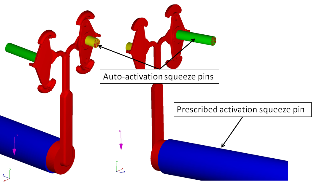
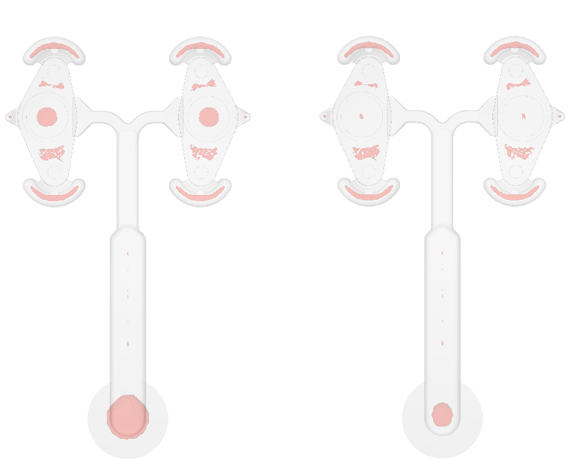
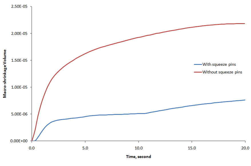
A case study was carried out on a two-cavity high pressure die casting. Two sets of simulations were run: one without squeeze pins, and one with squeeze pins. The configuration of the squeeze pins is shown in Fig. 1. One squeeze pin is placed at the center of each of the two casting parts. These squeeze pins are set to be automatically activated. The plunger is also defined as a squeeze pin, which is set to be activated immediately upon completion of filling. The resulting shrinkage distributions are shown in Fig. 2. The shrinkage reduction by the squeeze pins is obvious at the center of the castings and at the center of the biscuit. The total macro-shrinkage from the two simulations are also compared and plotted in Fig. 3, which quantitatively shows the dramatic shrinkage reductions by the squeeze pins.
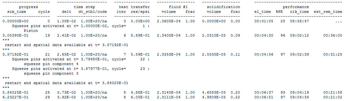
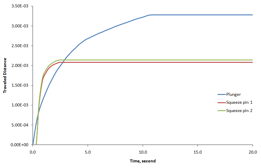
The time of the pin’s activation is written to the screen, HD3MSG, HD3OUT, and REPORT files, as shown in Fig. 4. The time information can be directly used as squeeze pin control parameters on high pressure die casting machines. In addition, the traveled distance and displaced volume by each squeeze pin are also written to the general history data, which can be used to verify the effectiveness of each squeeze pin. As shown in Fig. 5, the traveled distances by each squeeze pin are plotted. It can be seen that the plunger moves immediately at the beginning of the simulation as prescribed, and moves the farthest and the longest due to the fact that near the plunger it is the last solidified region and yields the largest shrinkage. The two squeeze pins defined at the center of each of the two casting parts are activated at the same time, and traveled almost the same distance due to the symmetry of the casting and squeeze pin configuration.
With the increasing complexity of castings, shrinkage porosity due to poor feeding is often inevitable in large part sections, despite optimized gating and feeding systems and proper die temperature management. In high pressure and permanent mold castings, squeeze pins are frequently used to locally press the metal to reduce shrinkage porosity. However, the effectiveness of squeeze pins is highly dependent on their placement and on the timing of pressurization. In order to predict these real-world scenarios, a squeeze pin model has been developed in FLOW-3D CAST to help design and optimize the squeeze pin process parameters.
