
FLOW-3D POST Playlist
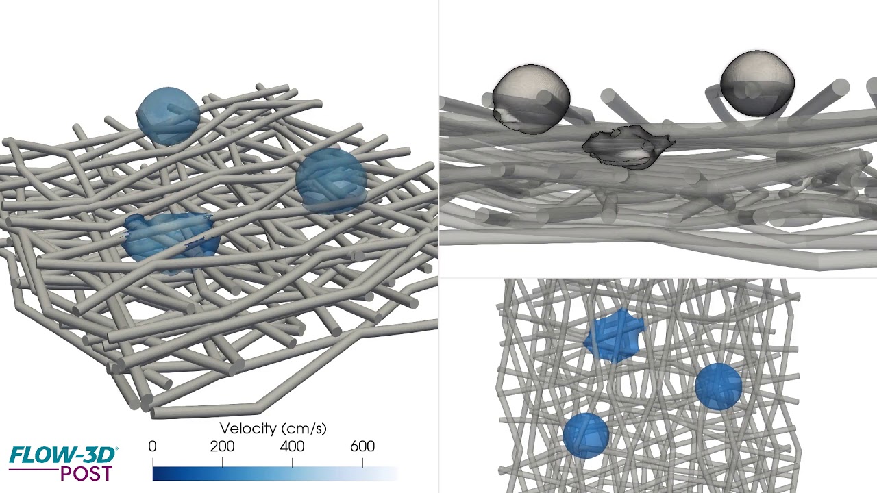

Here, FLOW-3D is used to simulate drop impingement on a fibrous bed, looking at the propagation of the fluid front as it relates to surface tension, contact angle, and viscosity.
Under certain flow conditions tangential dropshaft are effective by promoting the formation of a vortex core in the dropshaft as the flow is propagated to lower elevations. FLOW-3D HYDRO offers multiple modeling approaches to help engineers model free surface flow characteristics, and evaluate the energy dissipation, downdraft and air entrainment behaviors of the system.
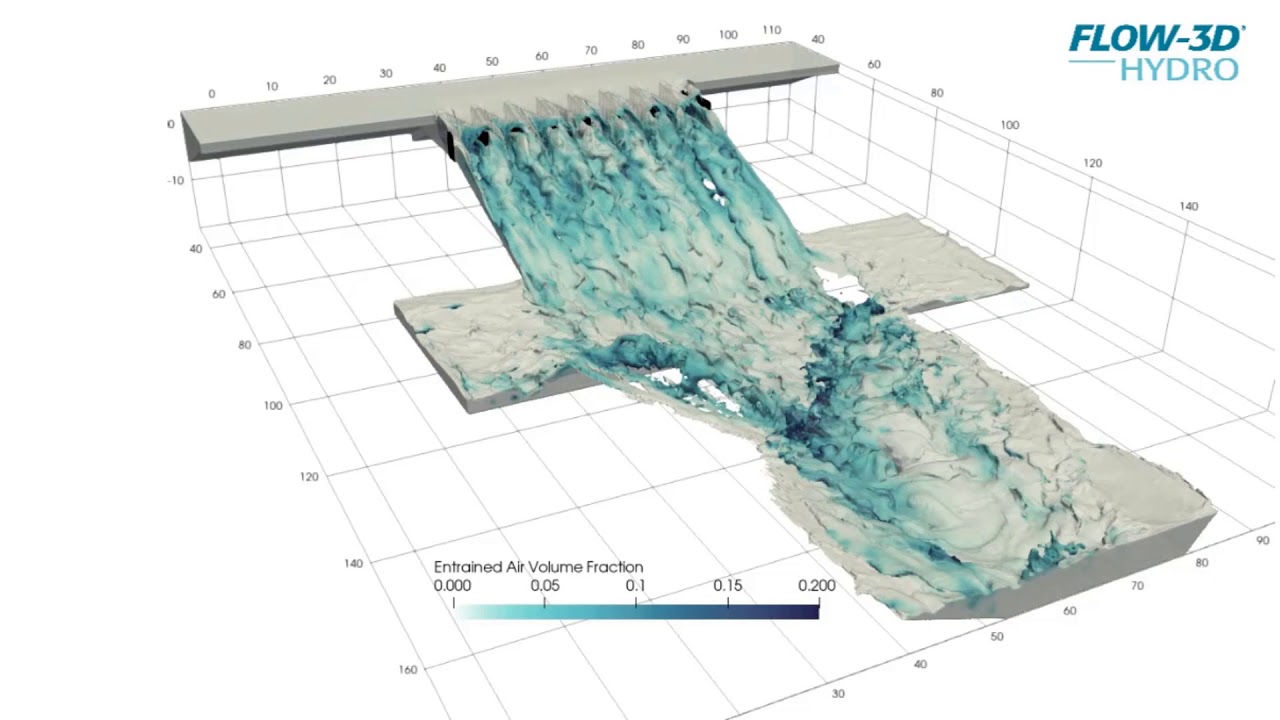
With the increased availability of high performance computing platforms, large scale simulation of complex free surface flows can now include very high meshing density, which delivers for the user a very high accuracy representation of the flow. This labyrinth weir model includes the free surface flow, as well as an estimate of air entrainment.
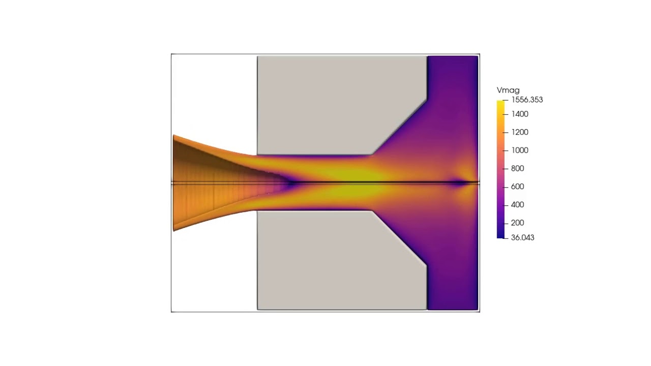
In this CFD simulation of a swirl spray nozzle, postprocessed with FLOW-3D POST, fluid spins at a high velocity before the nozzle. When fluid exits the nozzle, the centrifugal force sends the fluid away from the axis, creating a vortex core inside the nozzle.
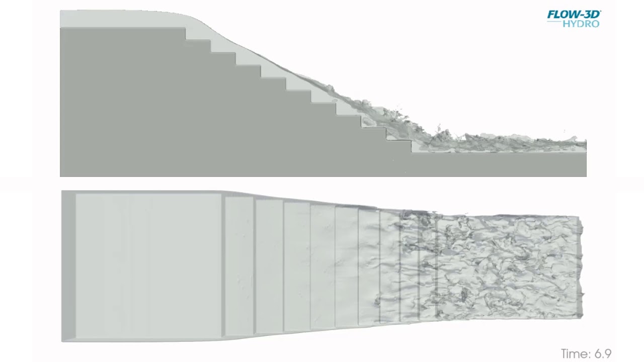
Turbulence generated from the solid surface of a staircase spillway can eventually propagate all the way to reach the free surface, at which point the flow may become highly aerated from that inception onwards. FLOW-3D offers multiple approaches that allow engineers to characterize the onset of aeration and estimate subsequent bulking of the flow.
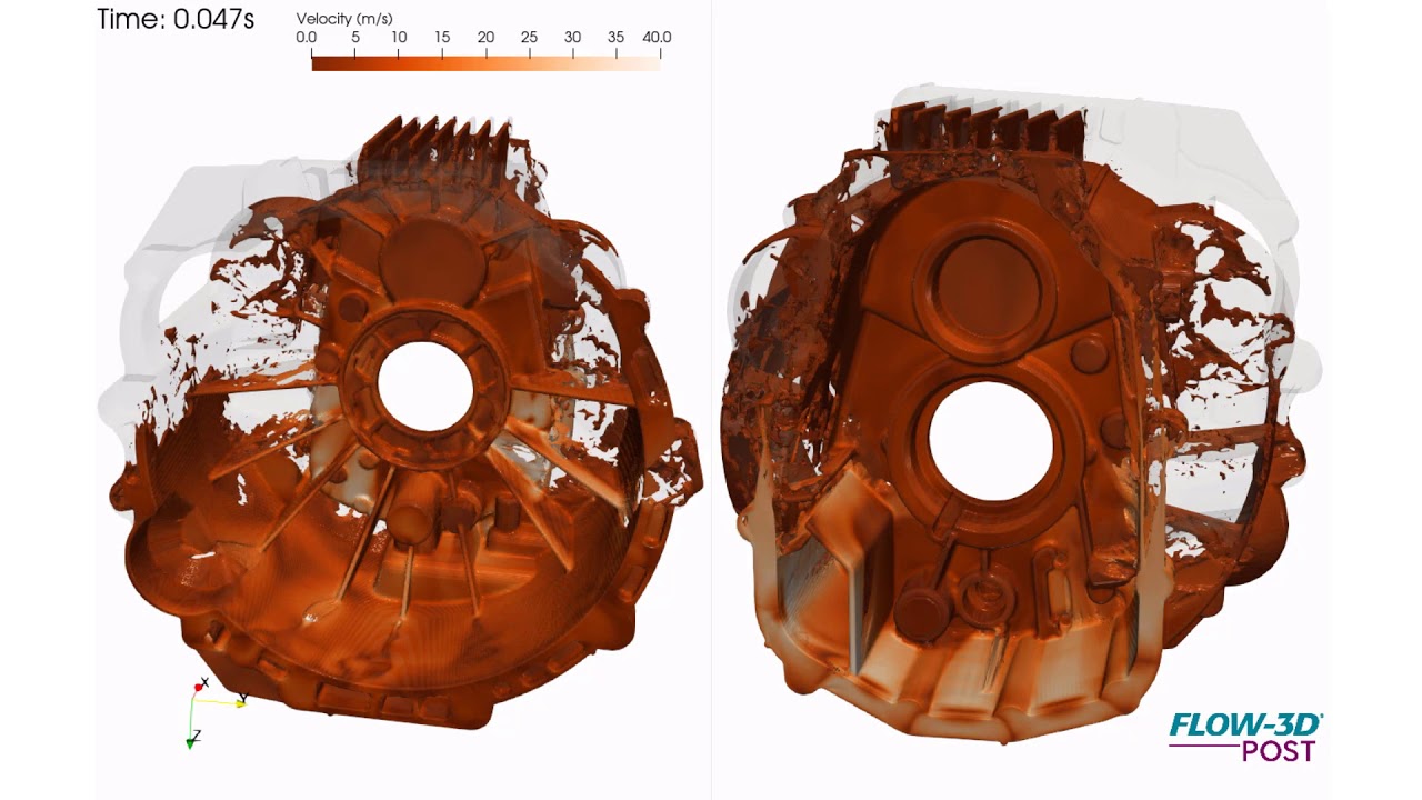
This is a simulation of an automotive flywheel or bell housing, showing velocity contours of aluminum alloy during fast shot of a high pressure die casting process. This is part of a design phase to evaluate different gating options, the 5 gates here simulate filling from a runner upward and below the parting line to accomplish 80-millisecond casting fill. The animation helps visualize the highly turbulent fill clearly indicating first and last regions to fill. Among other things, it helps in understanding the moving metal front and potential cold shots that result from this gating configuration.
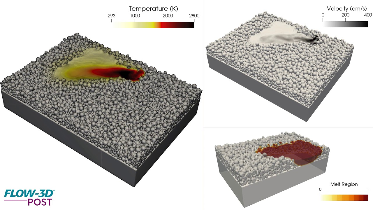
This simulation is looking at a L-PBF process in which the laser transverses the substrate in zigzag pattern. The remelting that occurs between tracks can influence the microstructure of the solidified metal, so it is important to understand how to optimize hatch spacing and scan strategy to achieve desired temperature gradients and cooling rates.
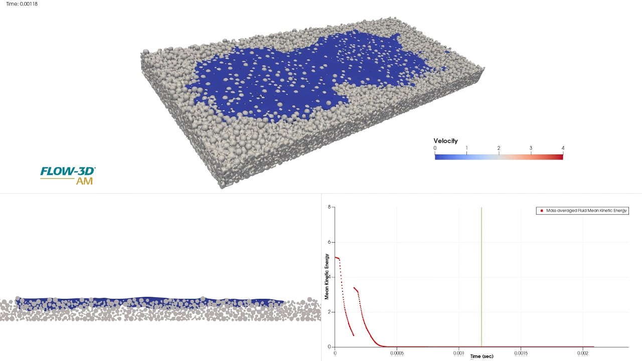
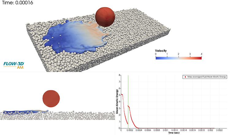
In this simulation, we look at fluid impact on a powder bed. The material properties of the fluid and the process parameters such as powder size distribution and droplet velocities influence the spreading, coalescence and penetration of the fluid into the powder bed. Capillary forces help the fluid to penetrate further into the powder bed. The mass-averaged kinetic energy plot shows that the fluid eventually reaches steady state indicating the depth of penetration and seepage into the medium. Learn more about modeling capillary action through CFD at www.flow3d.com.
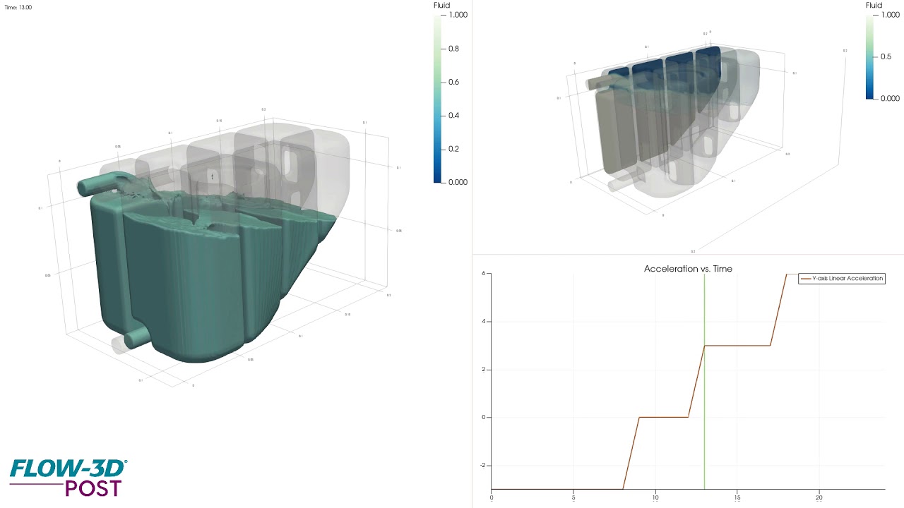
Degas bottles have been extensively used in engine coolant systems in automobiles, mainly to de-aerate the coolant fluid and provide room for expansion. This FLOW-3D simulation of a Degas bottle uses the full 2-fluid model to simulate both the coolant and air phases, which are represented with fluid fractions of 1 and 0 respectively. The video shows how the coolant in the system behaves under different vehicle accelerations.
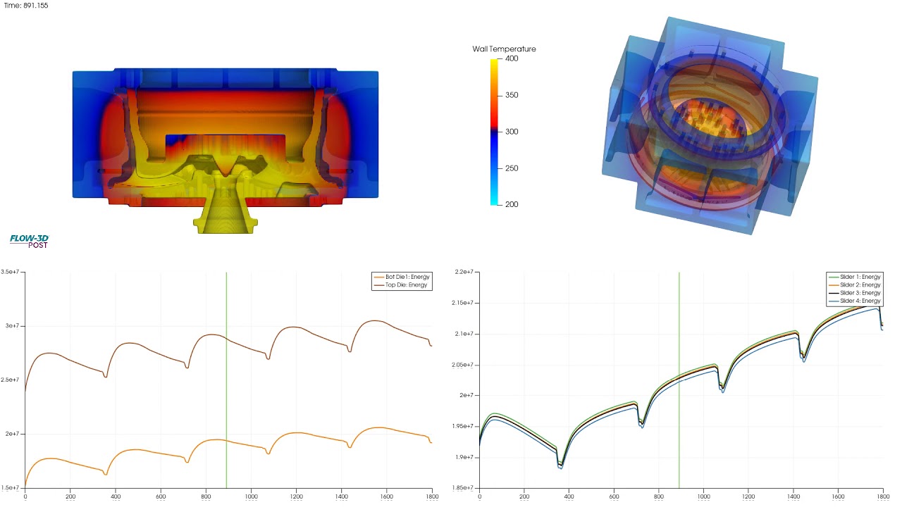
Thermal die cycling is used to heat the mold components to proper operating temperatures before starting production. Proper analysis of die thermal management protocols can inform extended die life and part quality. Simulation can be used to assess areas of heat saturation over many cycles. Additionally, once a thermal steady state has been determined, the profile can then be used to inform a filling simulation with greater accuracy.
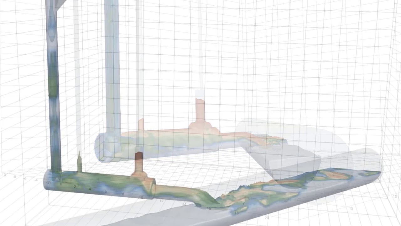
FLOW-3D POST ray trace rendering of a FLOW-3D HYDRO model of an energy dissipating baffled outlet. Learn more about FLOW-3D HYDRO‘s advanced CFD modeling solution for the civil and environmental engineering industry at www.flow3d.com/hydro
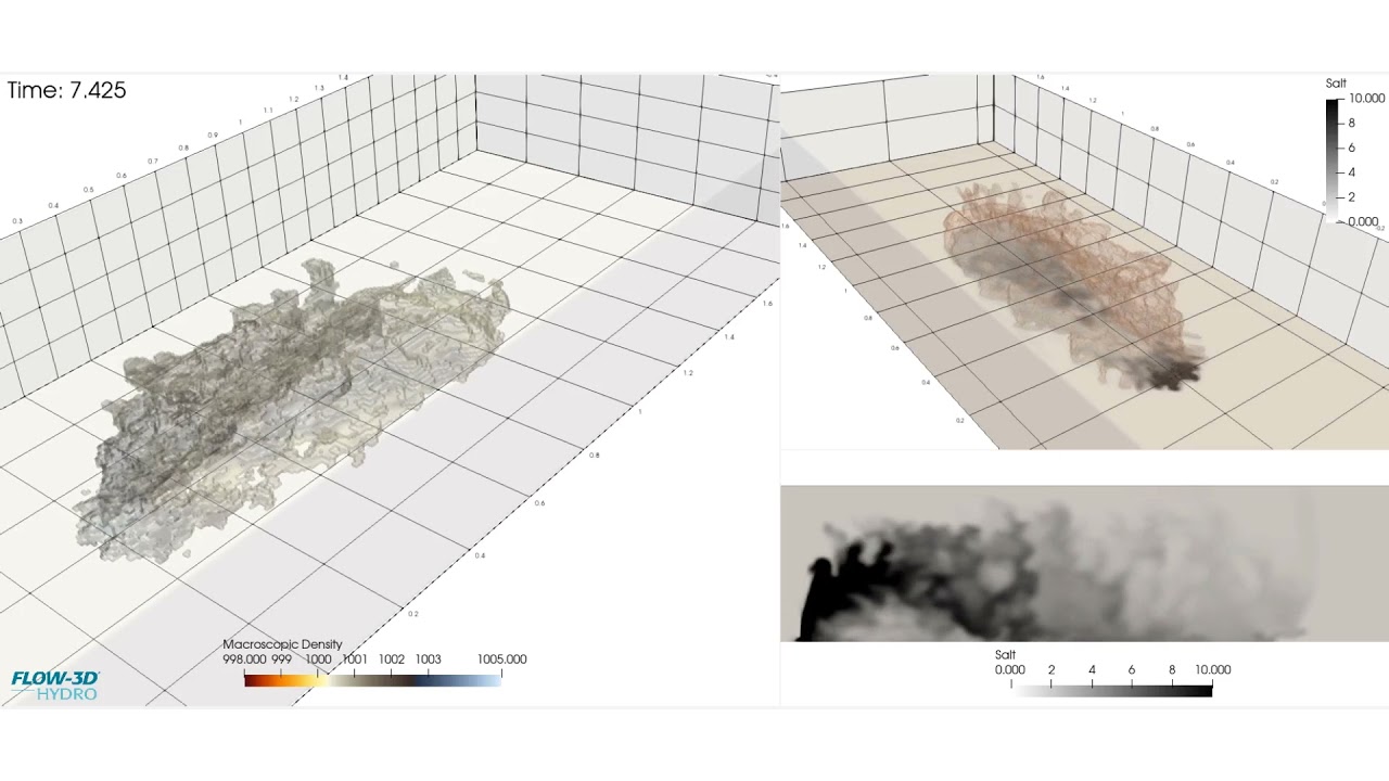
Rendering of a FLOW-3D HYDRO dense jet simulation, this visualization uses volume thresholds in FLOW-3D POST, Flow Science’s new postprocessor available across all FLOW-3D products.
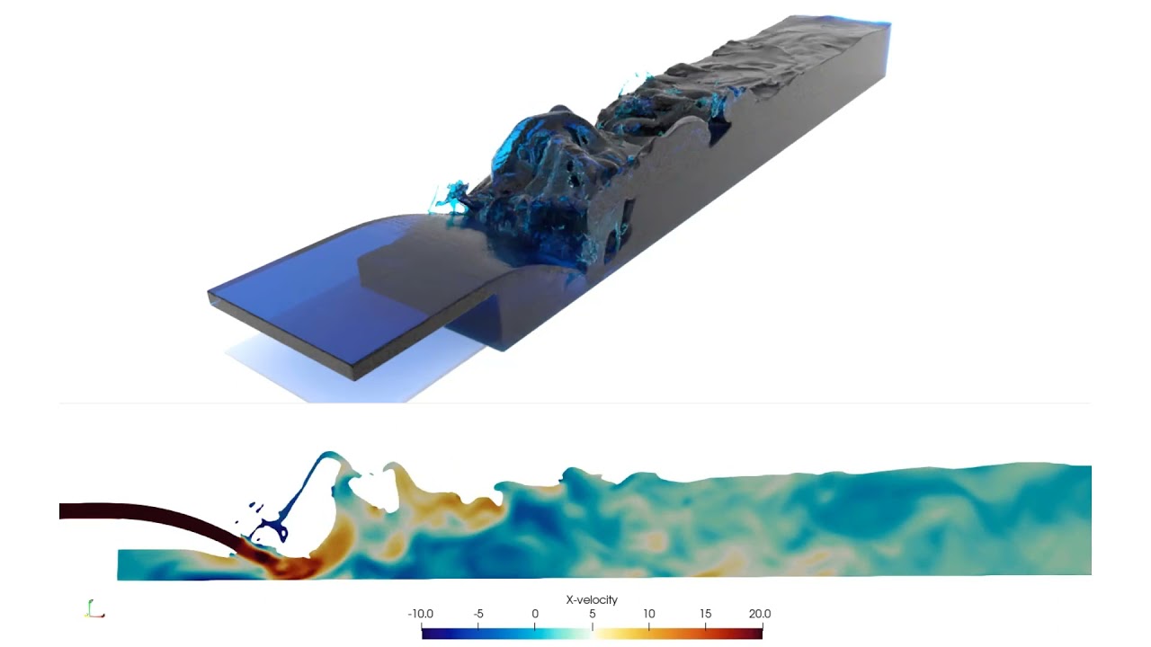
Development of a hydraulic jump simulated with FLOW-3D HYDRO. The top view is a ray-traced rendering of the flow; the bottom view, a 2D slice of the velocity field. This simulation was postprocessed with FLOW-3D POST, our new postprocessor for visualization and analysis across FLOW-3D products. Learn more at www.flow3d.com/hydro
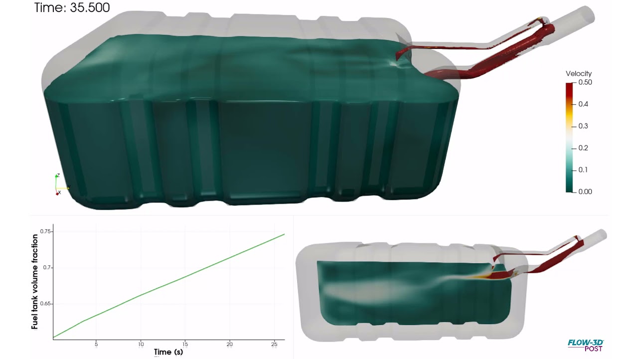
Automotive fuel tanks are designed to account for compressibility of fuel vapor while refueling and to prevent early shut-offs at fuel stations. This can cause shuddering of fuel vending units, eventually causing damage. Improper shut-offs can also cause fuel spillage or fire. Typically, fuel tank shapes are designed based on chassis or frame limitations. Shown here is a simulation of a simple fuel tank through refueling where a secondary vent tube (smaller tube on top) is simulated to allow fuel to completely fill the tank and initiate timely shutoff. This can be done either as a single and multi-fluid analysis in FLOW-3D, simulating vapor backpressure and fuel flow. The animation shows velocity contours of fuel and volume fraction of the fuel tank being filled.
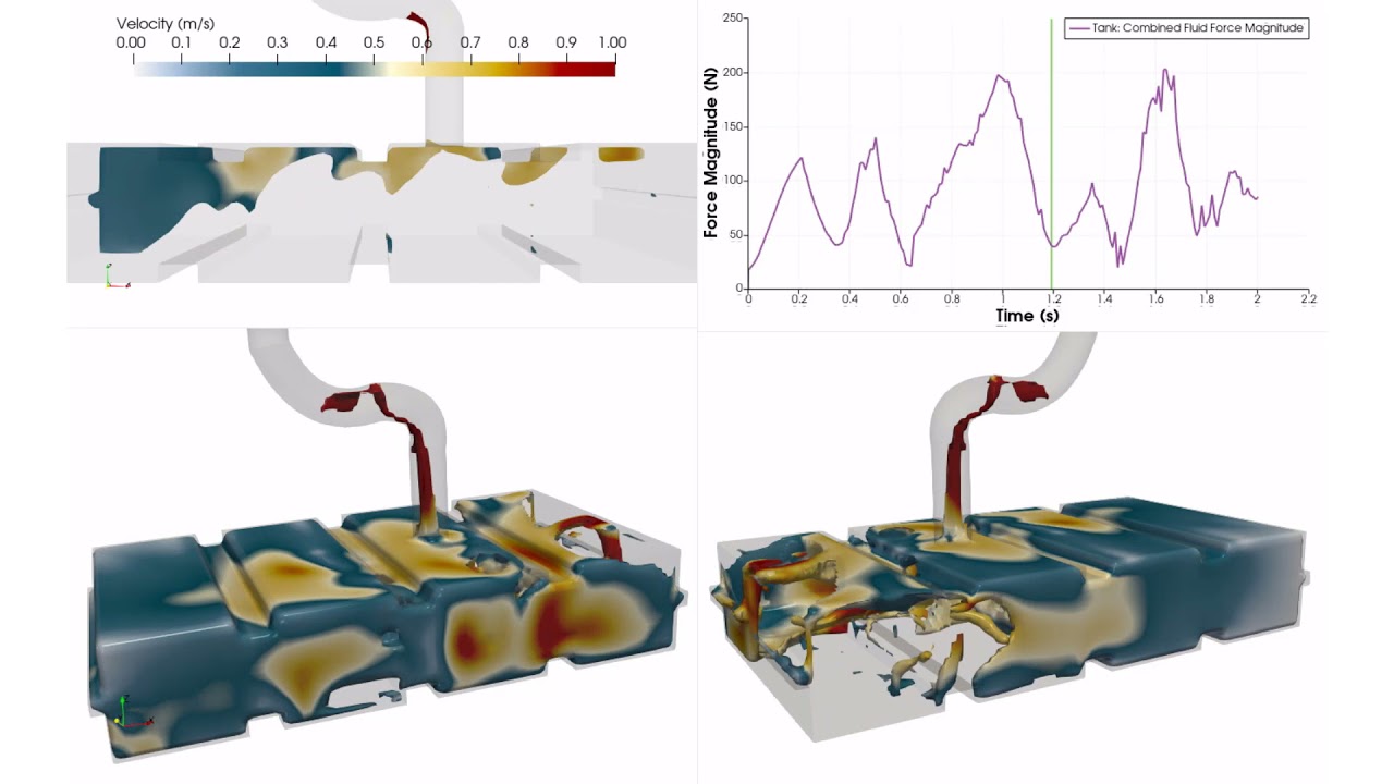
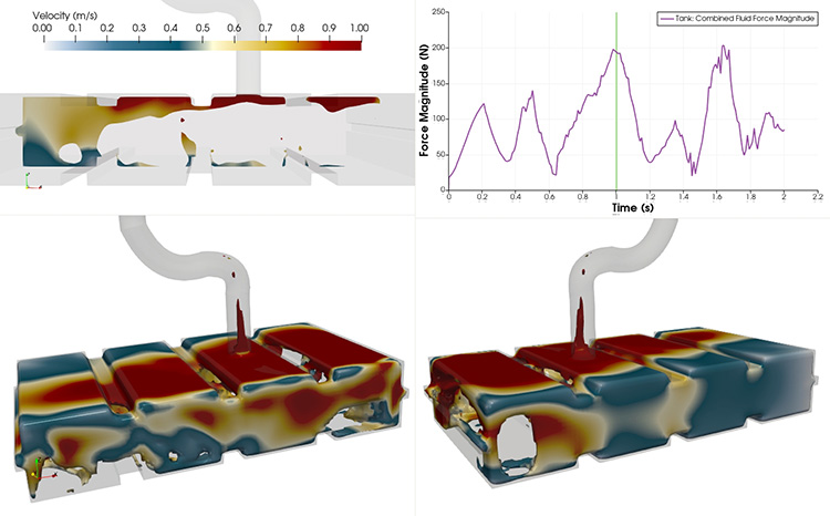
Automotive fuel tanks hold significant fuel mass and are subject to constant vehicle accelerations and decelerations. This presents a structural issue for tank material due to the impact forces. Additionally, sloshing of fuel can cause incorrect reading or damage to measurement devices. Shown here is a simulation in FLOW-3D of fuel sloshing under acceleration plotting velocity contours. The graph shows transient force magnitude on fuel tank.


Kitware collaborates with customers to solve the world’s most complex scientific challenges through custom software solutions based on open source technology, such as ParaView and the Visualization Toolkit. Kitware’s technical computing experts develop effective and powerful software that adds value to both industry and user communities.
