
FLOW-3D Playlist
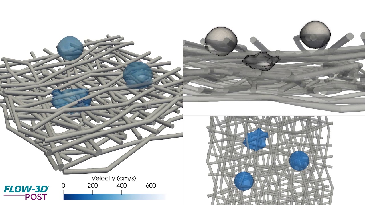


Here, FLOW-3D is used to simulate drop impingement on a fibrous bed, looking at the propagation of the fluid front as it relates to surface tension, contact angle, and viscosity.
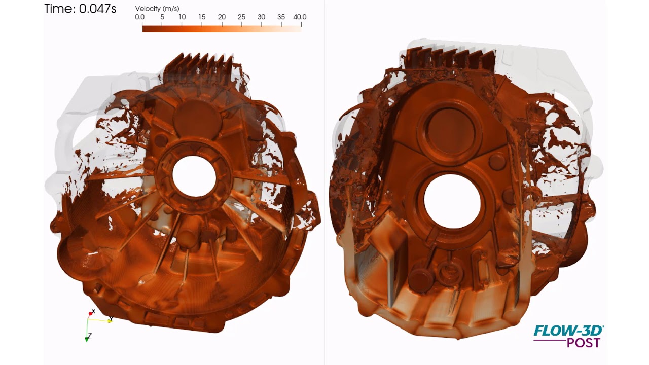
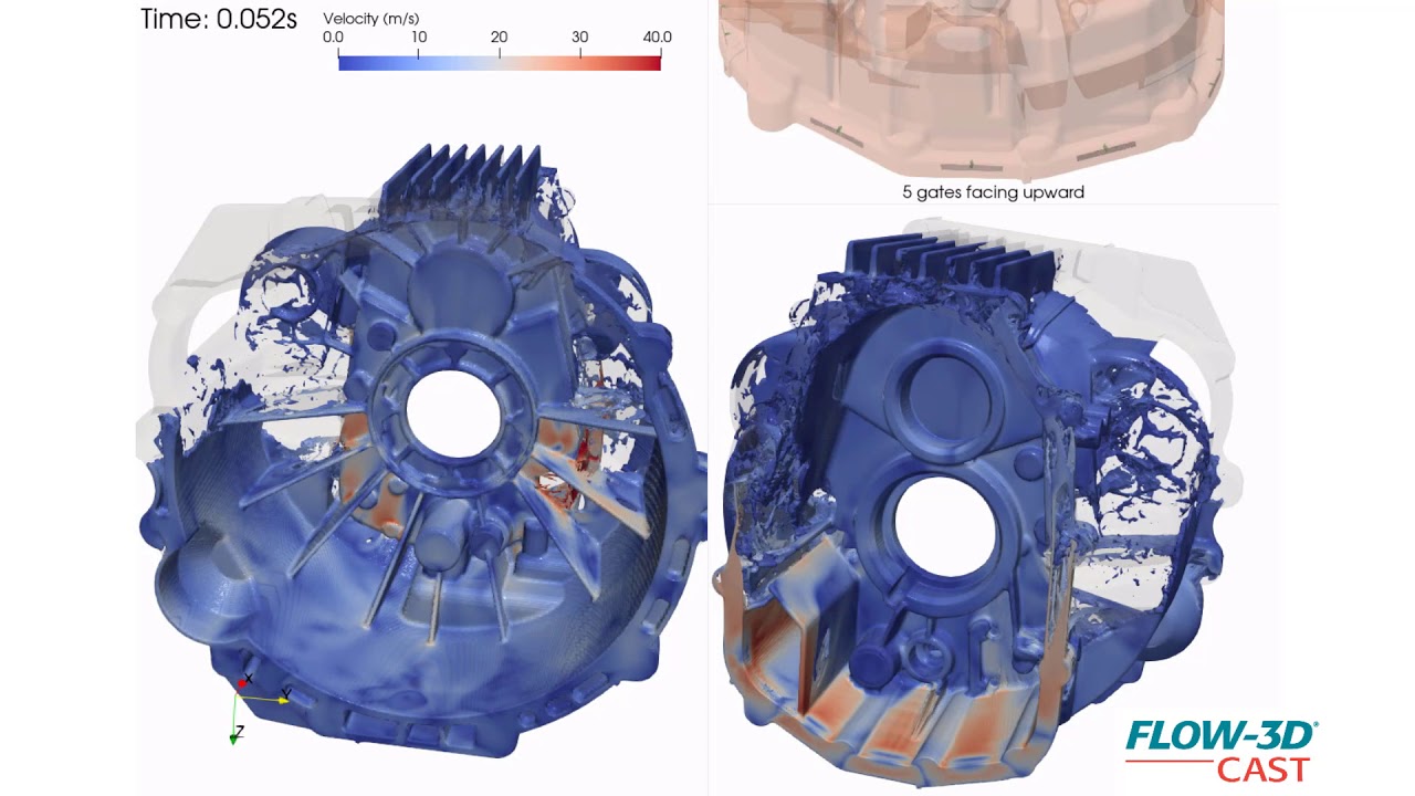
This is a simulation of an automotive flywheel or bell housing, showing velocity contours of aluminum alloy during fast shot of a high pressure die casting process. This is part of a design phase to evaluate different gating options, the 5 gates here simulate filling from a runner upward and below the parting line to accomplish 80-millisecond casting fill. The animation helps visualize the highly turbulent fill clearly indicating first and last regions to fill. Among other things, it helps in understanding the moving metal front and potential cold shots that result from this gating configuration.
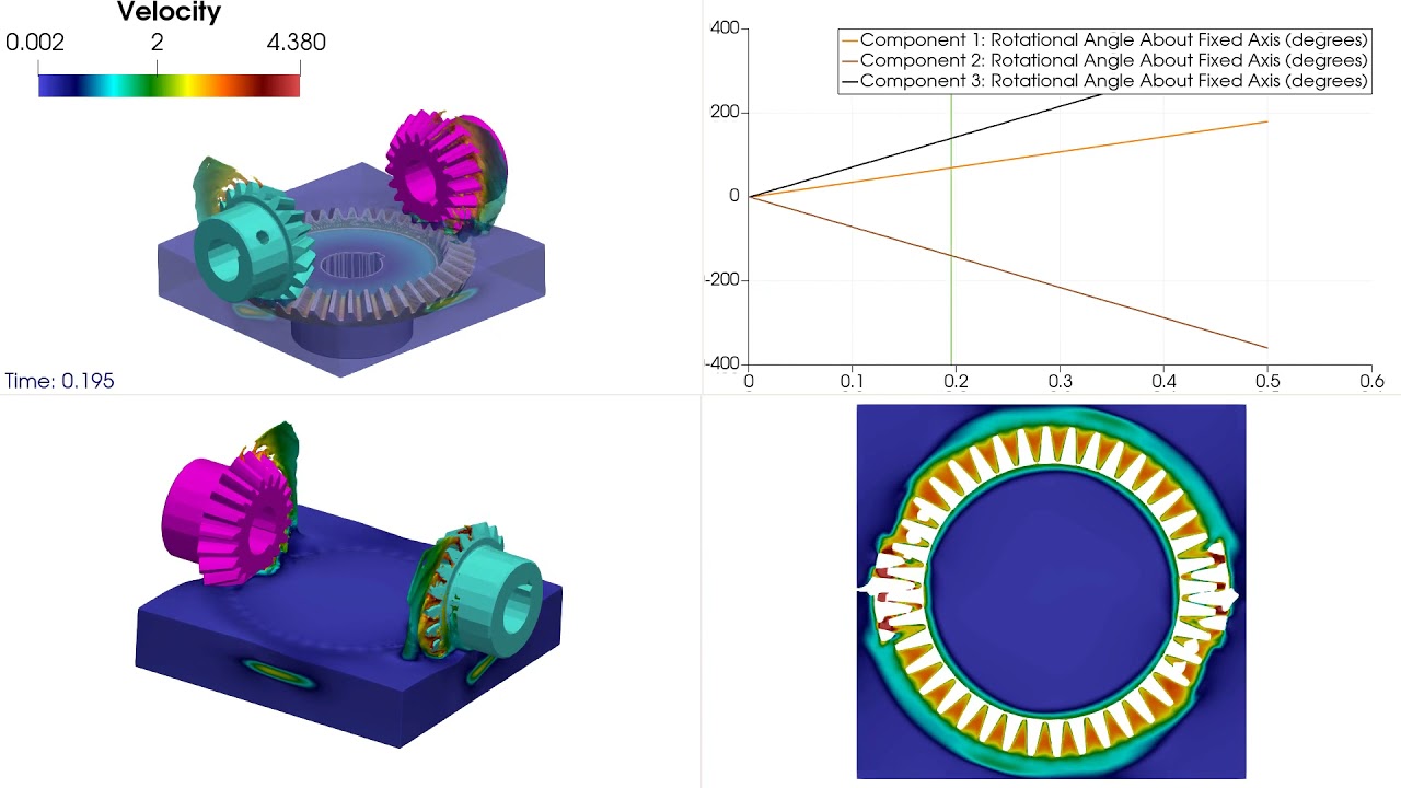
This simulation depicts gear-gear and gear-oil interactions in a gear box as an example of fluid-structure interaction. The left gear possesses prescribed rotation. The two gears undergo a series of collisions with each other on their teeth causing rotation of the right gear. The right gears rotation is also affected by its interaction with the motion of the oil.
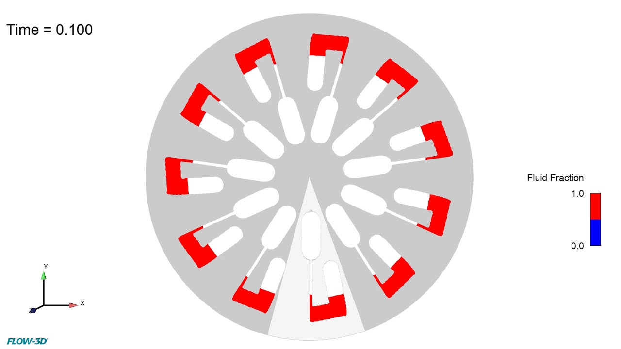
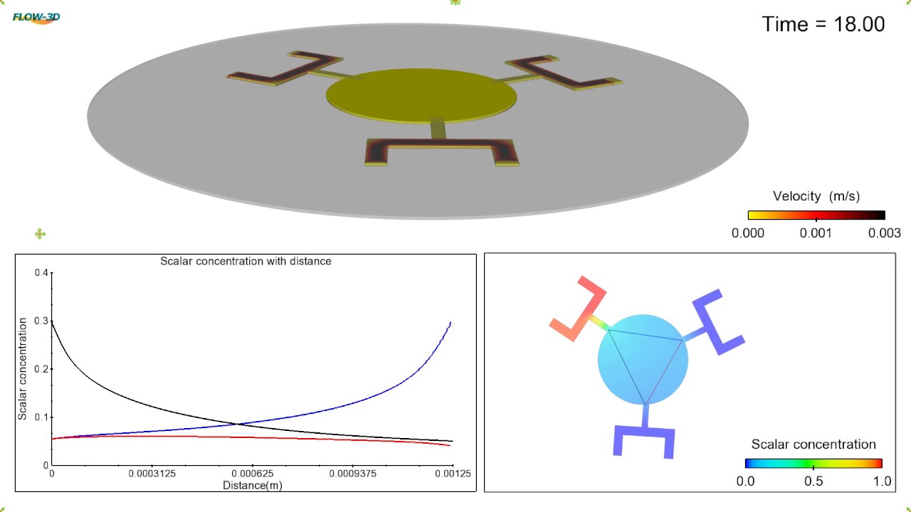
This FLOW-3D simulation shows the kinetic energy fluctuations for a microfluidic compact disc rotating at 7000 rpm. At this rotation speed, compared to the 1000 rpm speed (https://youtu.be/stAYg1nAr2E), steady state is reached faster but with rapidly fluctuating water levels. Read the blog.
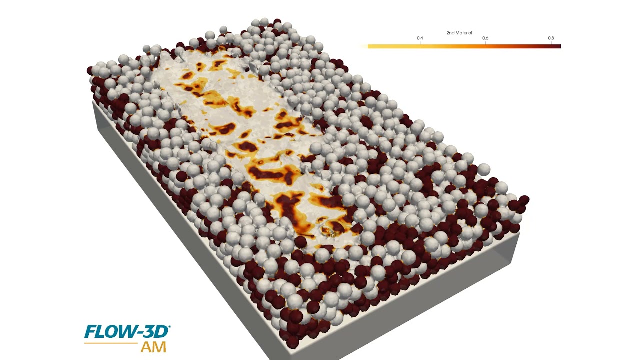
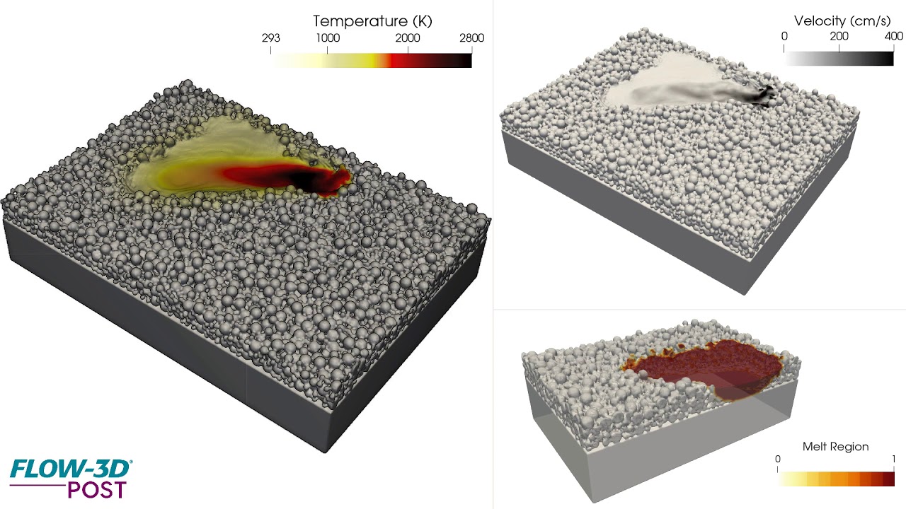
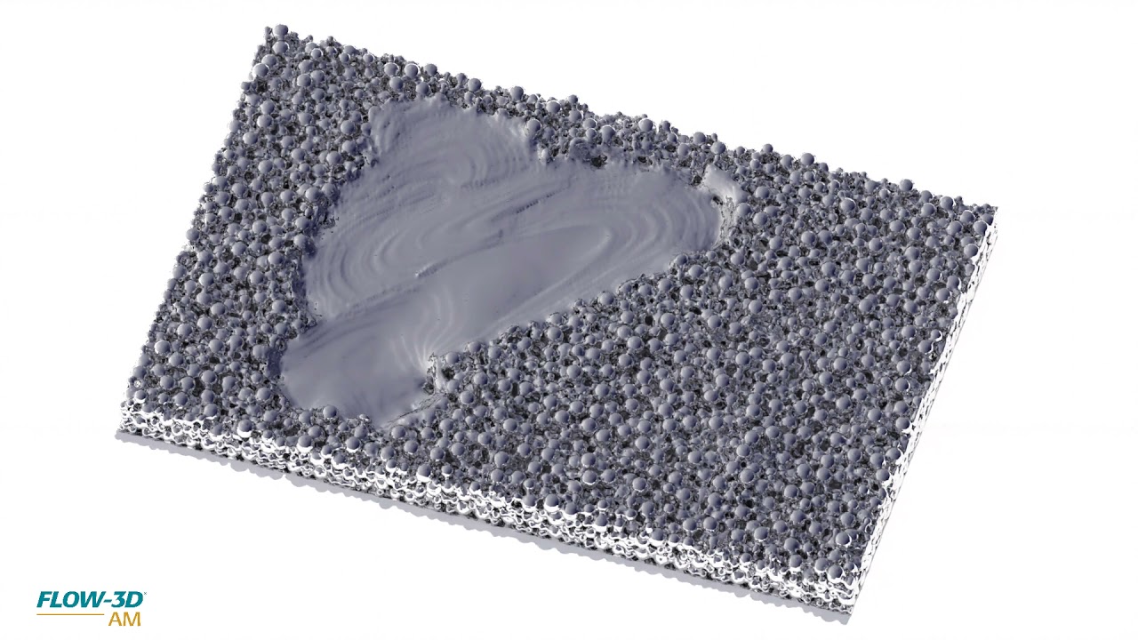
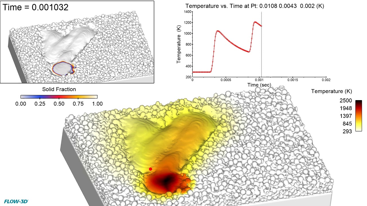
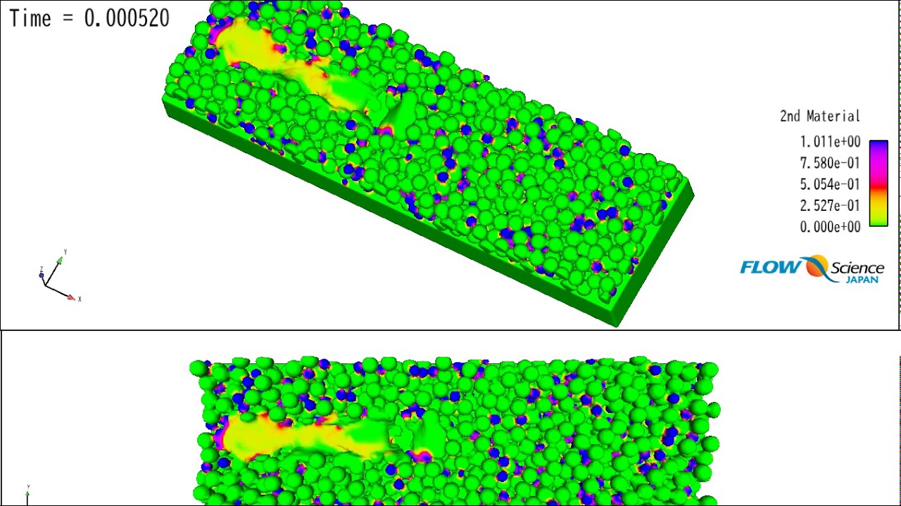
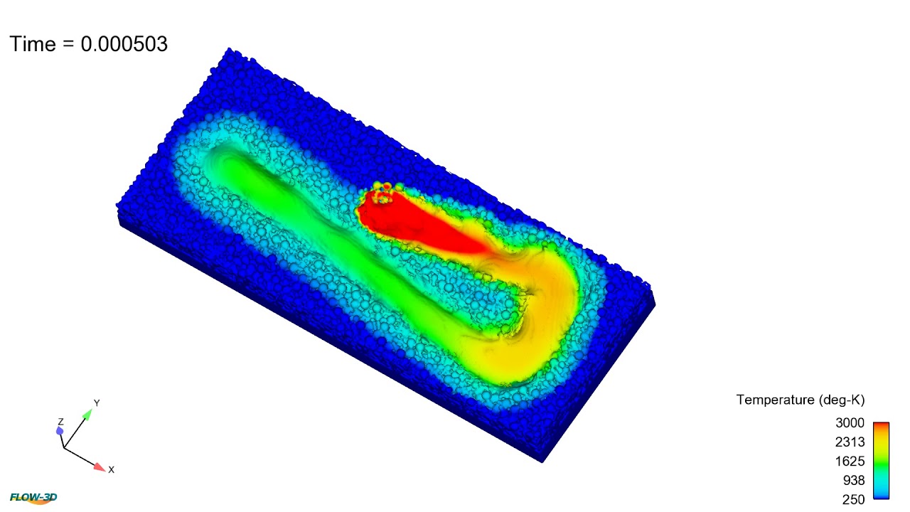
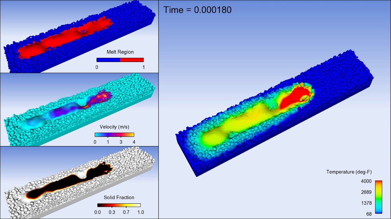
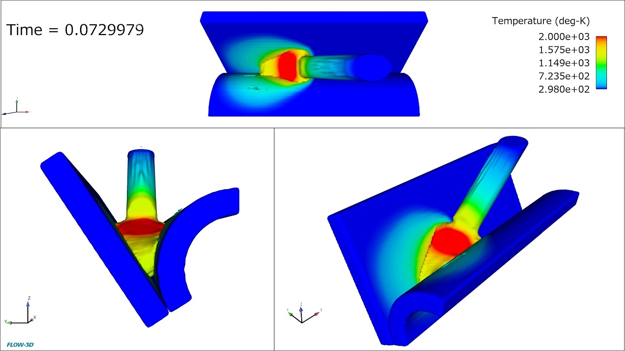
Micro and meso scale simulations using FLOW-3D AM help us understand the mixing of different materials in the melt pool and the formation of potential defects such as lack of fusion and porosity. In this simulation, the stainless steel and aluminum powders have independently-defined temperature dependent material properties that FLOW-3D AM tracks to accurately capture the melt pool dynamics.
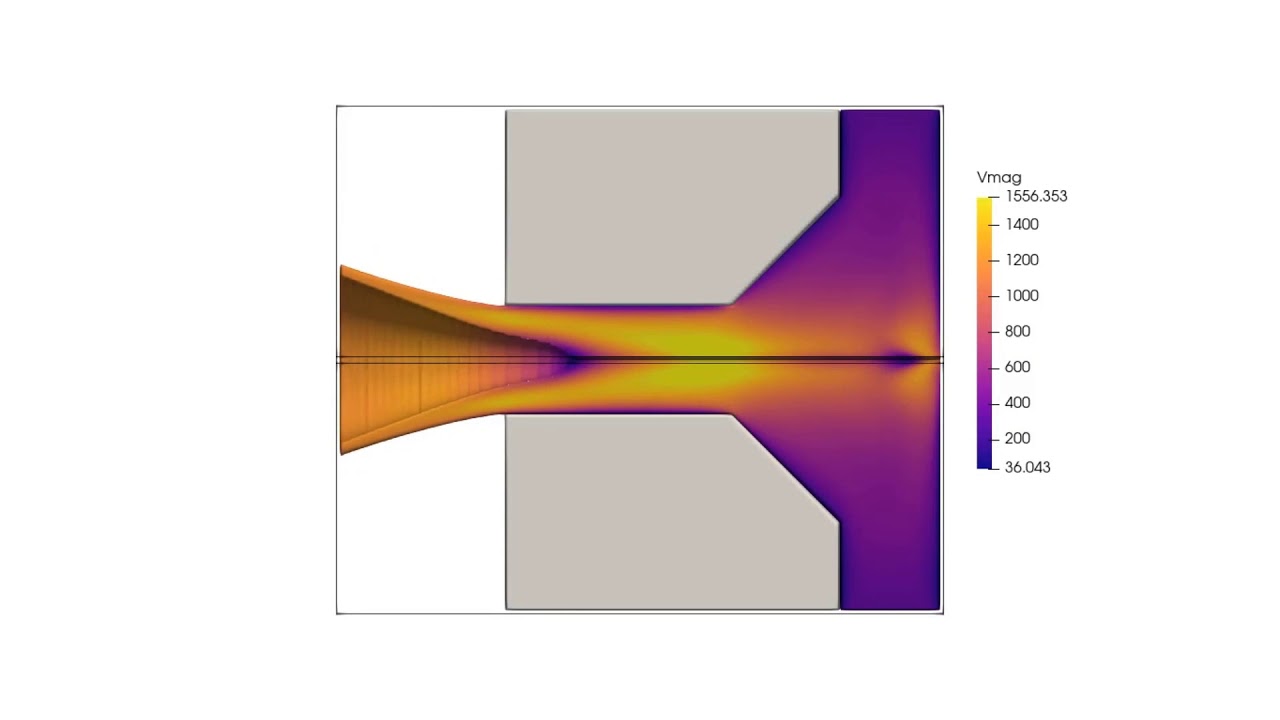
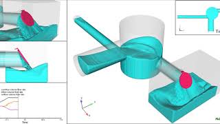
In this CFD simulation of a swirl spray nozzle, postprocessed with FLOW-3D POST, fluid spins at a high velocity before the nozzle. When fluid exits the nozzle, the centrifugal force sends the fluid away from the axis, creating a vortex core inside the nozzle.
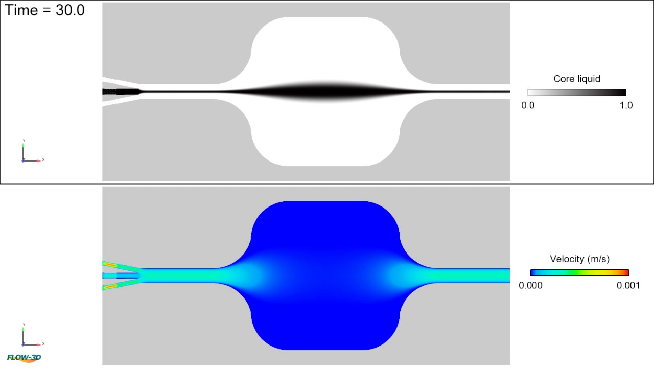
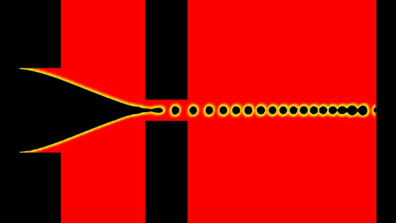
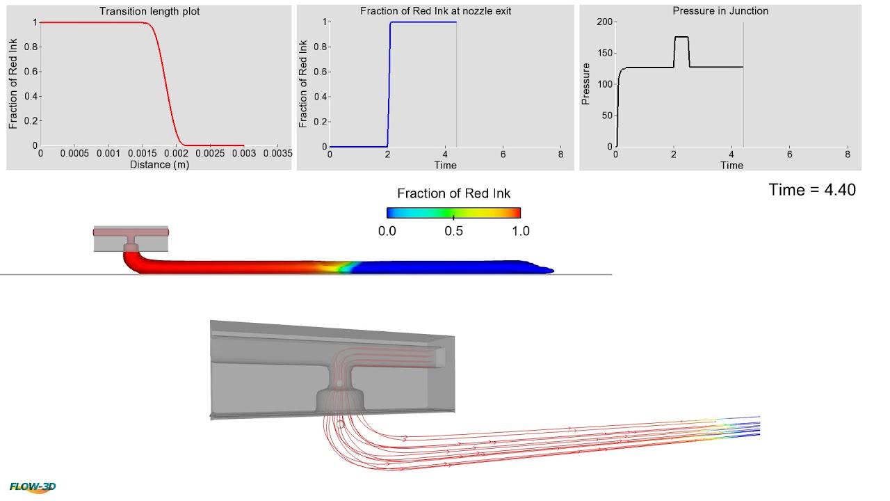
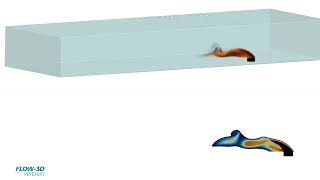
Animation showing the formation of biconvex shape lens using a core flow (black fluid) rate of 3 mL/h and cladding flow (white) rates of 7 mL/h.
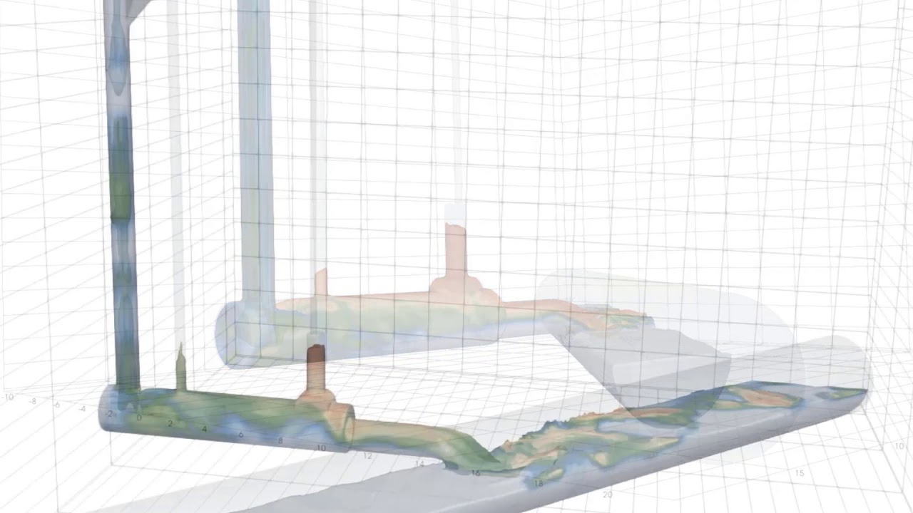
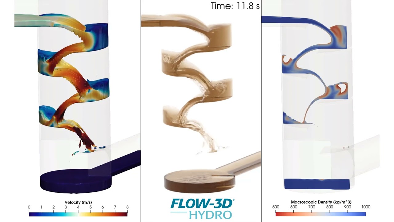
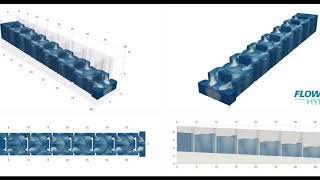
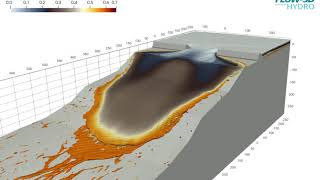
Under certain flow conditions tangential dropshaft are effective by promoting the formation of a vortex core in the dropshaft as the flow is propagated to lower elevations. FLOW-3D HYDRO offers multiple modeling approaches to help engineers model free surface flow characteristics, and evaluate the energy dissipation, downdraft and air entrainment behaviors of the system.
Flow focusing is a microfluidics technique to generate droplets or bubbles using hydrodynamics. In this video, FLOW-3D is used to simulate the flow focusing process.
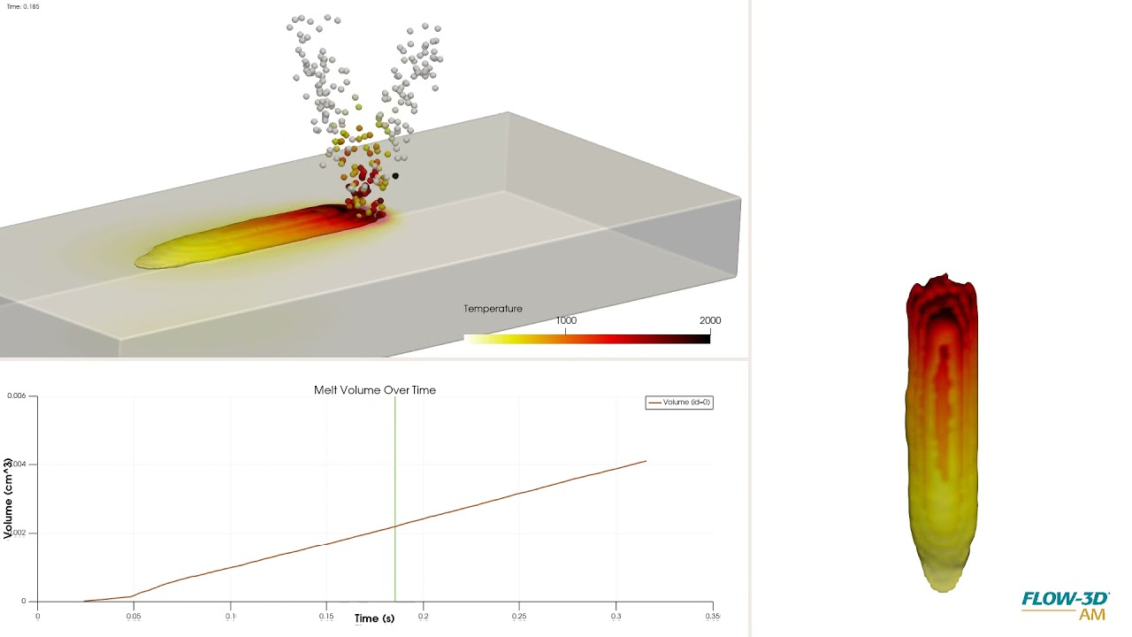
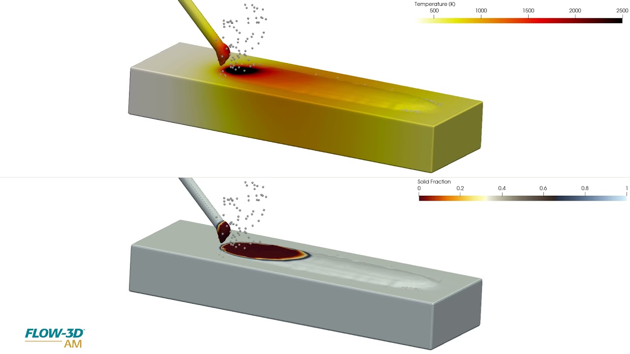
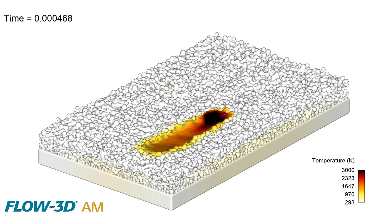
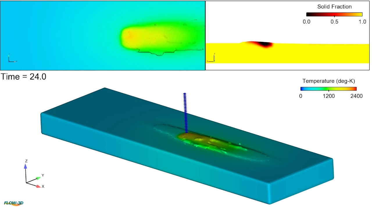
In this FLOW-3D AM simulation of a powder-based directed energy deposition process, powder particles are melted onto a substrate by way of a laser. Tracks are laid next to and on top of eachother where they solidify to build a 3D part. This simulation can be used to study the influence of process parameters like laser power, powder injection rates, scan speeds and material properties on fusion and subsequent mechanical properties.
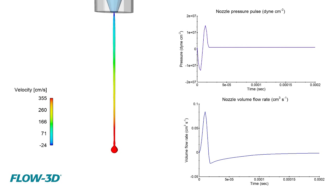
This simulation is looking at droplet ejection of a piezo driven inkjet. These drop-on-demand (DoD) printheads are used for a variety of applications from conventional printing processes to additive manufacturing processes such as binder jetting and material deposition. FLOW-3D allows for analysis of how system parameters and fluid rheology affect droplet velocities, uniformity, and overall consistency in the printed image or part.
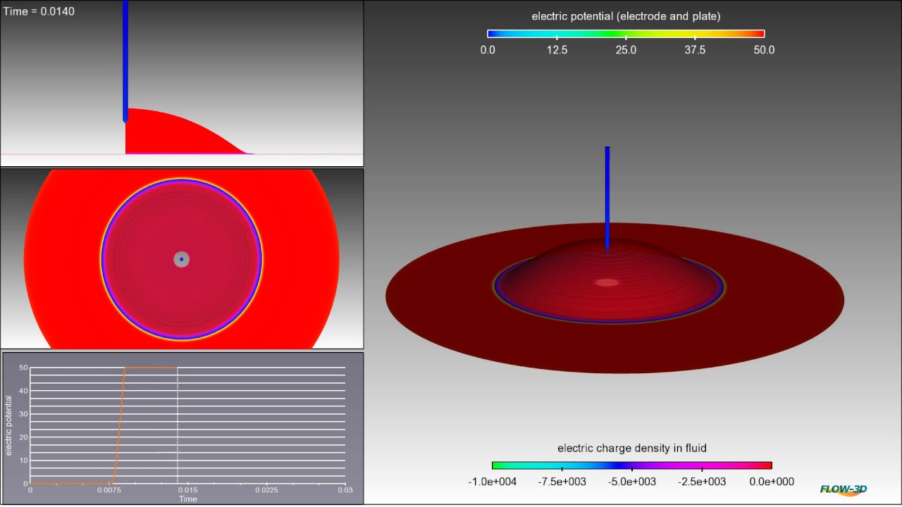
Electrowetting is a technique used to change the apparent contact angle of a dielectric fluid under the influence of electric potential. In this example, the fluid is originally hydrophobic and beads on the surface. However, when a 50V potential difference is applied, the fluid is forced to wet the surface becoming hydrophilic.
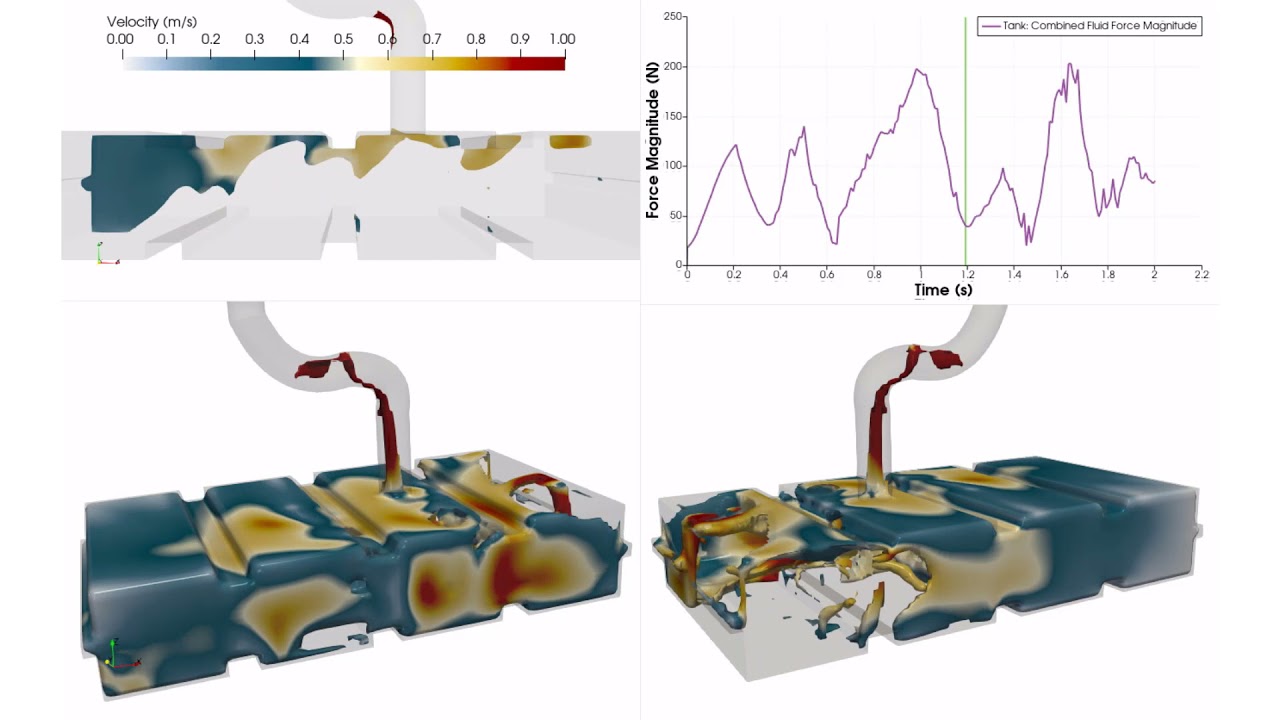
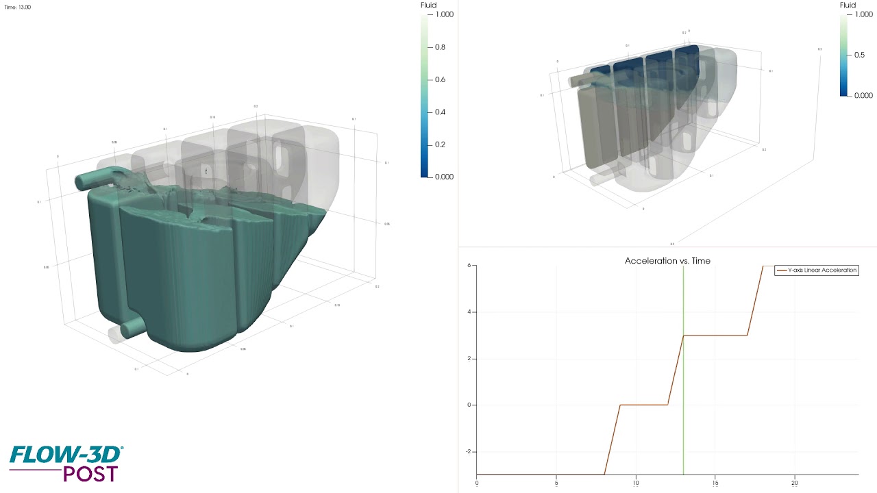
Automotive fuel tanks hold significant fuel mass and are subject to constant vehicle accelerations and decelerations. This presents a structural issue for tank material due to the impact forces. Additionally, sloshing of fuel can cause incorrect reading or damage to measurement devices. Shown here is a simulation in FLOW-3D of fuel sloshing under acceleration plotting velocity contours. The graph shows transient force magnitude on fuel tank.
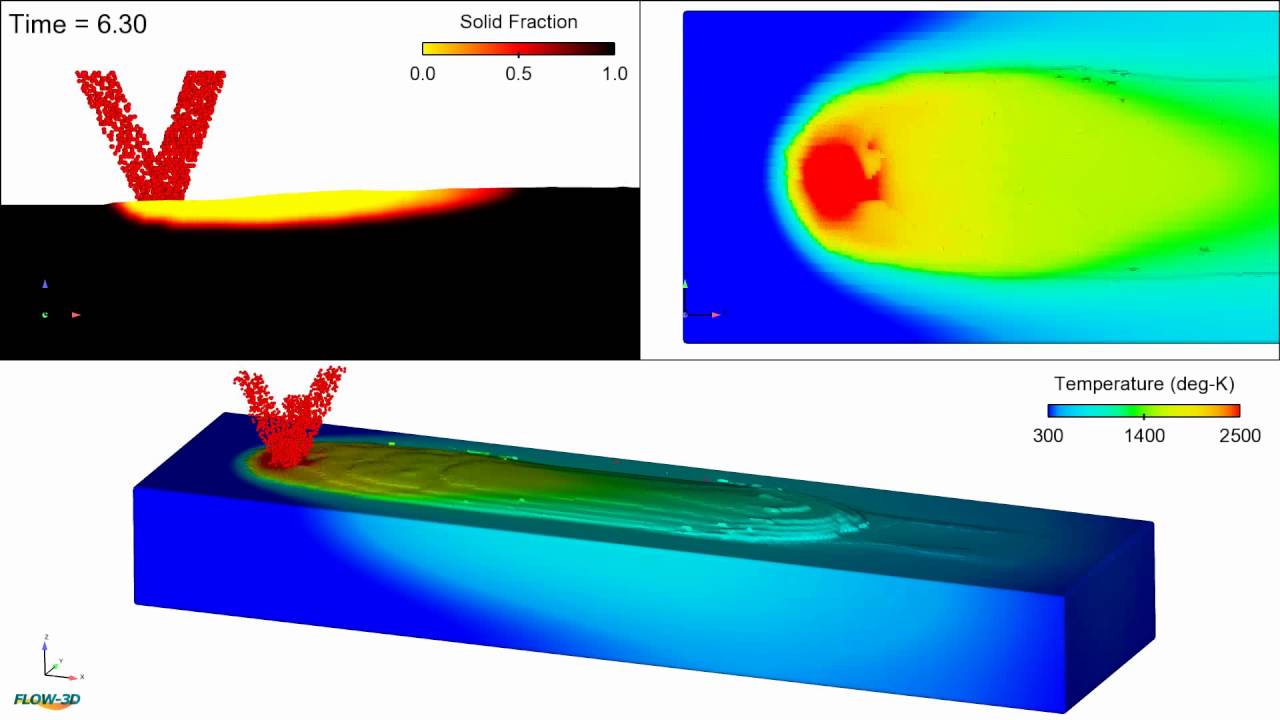
In this FLOW-3D AM simulation of a wire/powder-based directed energy deposition process, powder particles and wire feed are melted onto a substrate by way of a laser. Tracks are laid next to and on top of each other where they solidify to build a 3D part. This simulation can be used to study the influence of process parameters like laser power, powder injection rates, wires feed rates, scan speeds and material properties on fusion and subsequent mechanical properties.
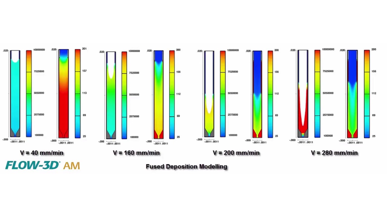
Fused Deposition Modeling (FDM) is one of the most widely used 3D printing techniques, but not much research has been done on polymer extrusion and flow characterization. How do extrusion speeds and nozzle geometries affect the FDM process? This is a question that researchers from Technical University of Denmark tried to answer using CFD models built in FLOW-3D AM. This simulation video shows the polymer flow within the liquifier at different extrusion speeds. At speeds greater than 160 mm/min, oscillations set in and the process becomes unstable. A recirculation zone forms near the interface of the solid filament and the melt zone, which prevents the polymer melt from flowing upstream.
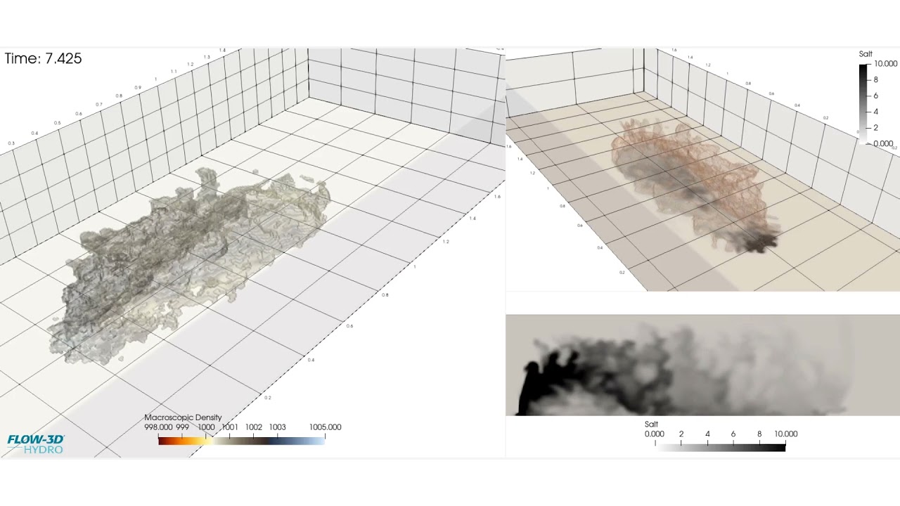
Rendering of a FLOW-3D HYDRO dense jet simulation, this visualization uses volume thresholds in FLOW-3D POST, Flow Science’s new postprocessor available across all FLOW-3D products.
This FLOW-3D simulation of a 2-D microfluidic palette demonstrates a spatio-temporal control on the generated gradients. The source and sink are rotated at an angular velocity. Also, after every t seconds, the active access port is deactivated and the next port is turned on. To see the live status of the diffusion inside the chamber, three line probes are placed in the simulation (marked in red, blue and black, respectively, in the bottom right window of the simulation). Read the blog.
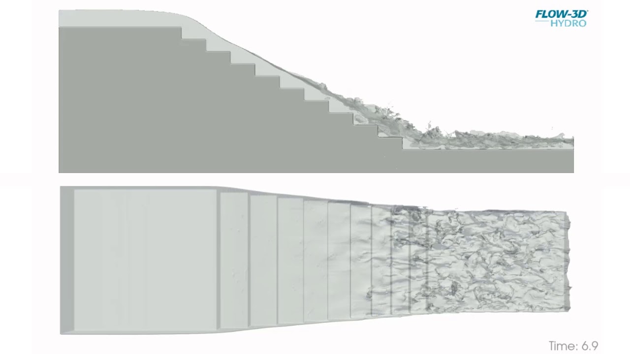
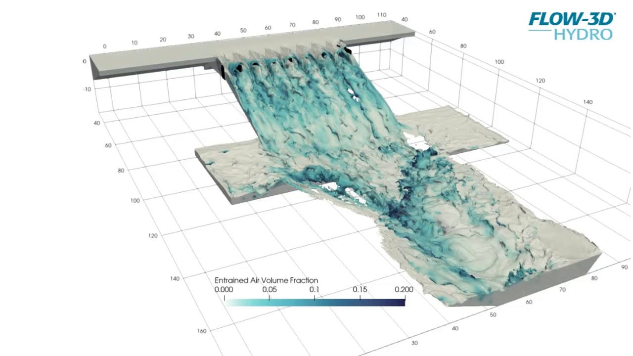
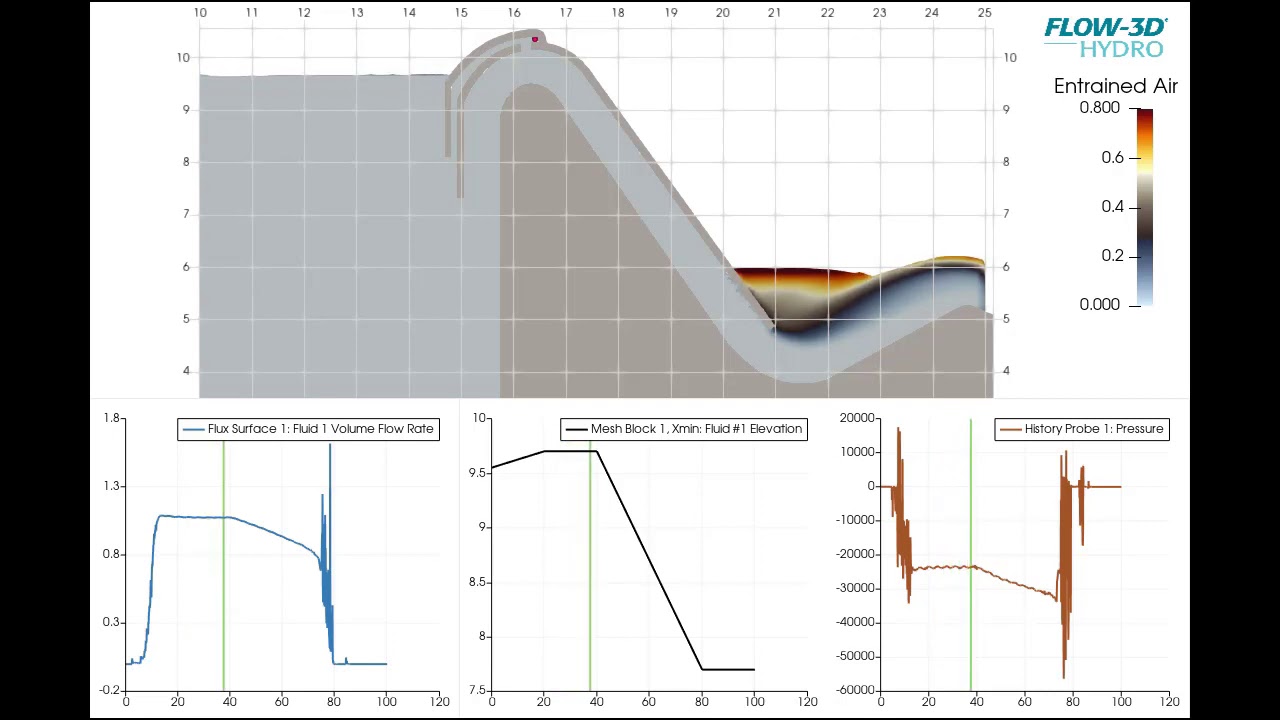
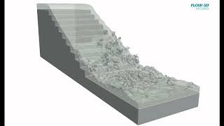
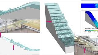
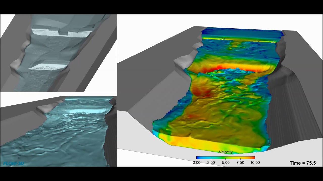
Turbulence generated from the solid surface of a staircase spillway can eventually propagate all the way to reach the free surface, at which point the flow may become highly aerated from that inception onwards. FLOW-3D offers multiple approaches that allow engineers to characterize the onset of aeration and estimate subsequent bulking of the flow.
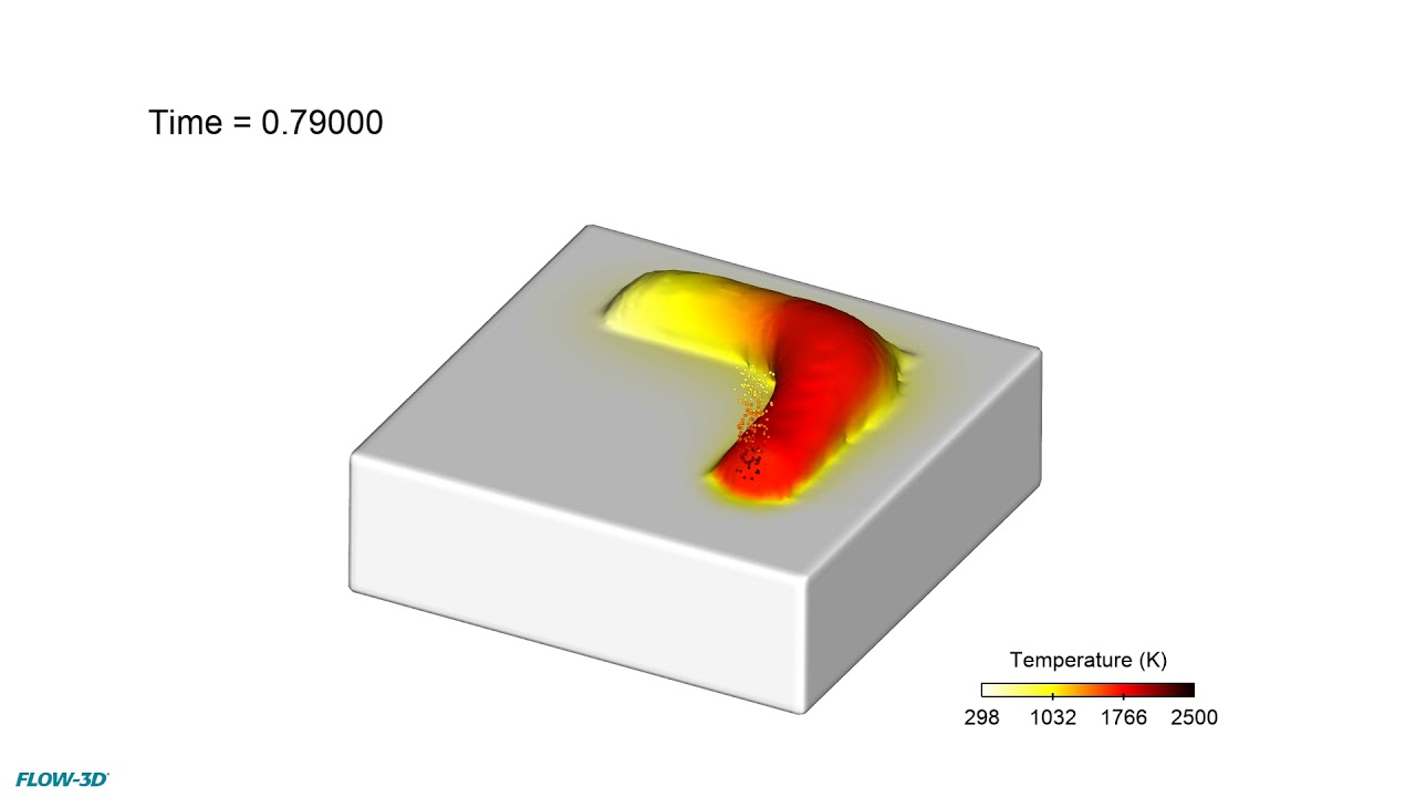
This simulation is looking at a L-PBF process in which the laser transverses the substrate in zigzag pattern. The remelting that occurs between tracks can influence the microstructure of the solidified metal, so it is important to understand how to optimize hatch spacing and scan strategy to achieve desired temperature gradients and cooling rates.
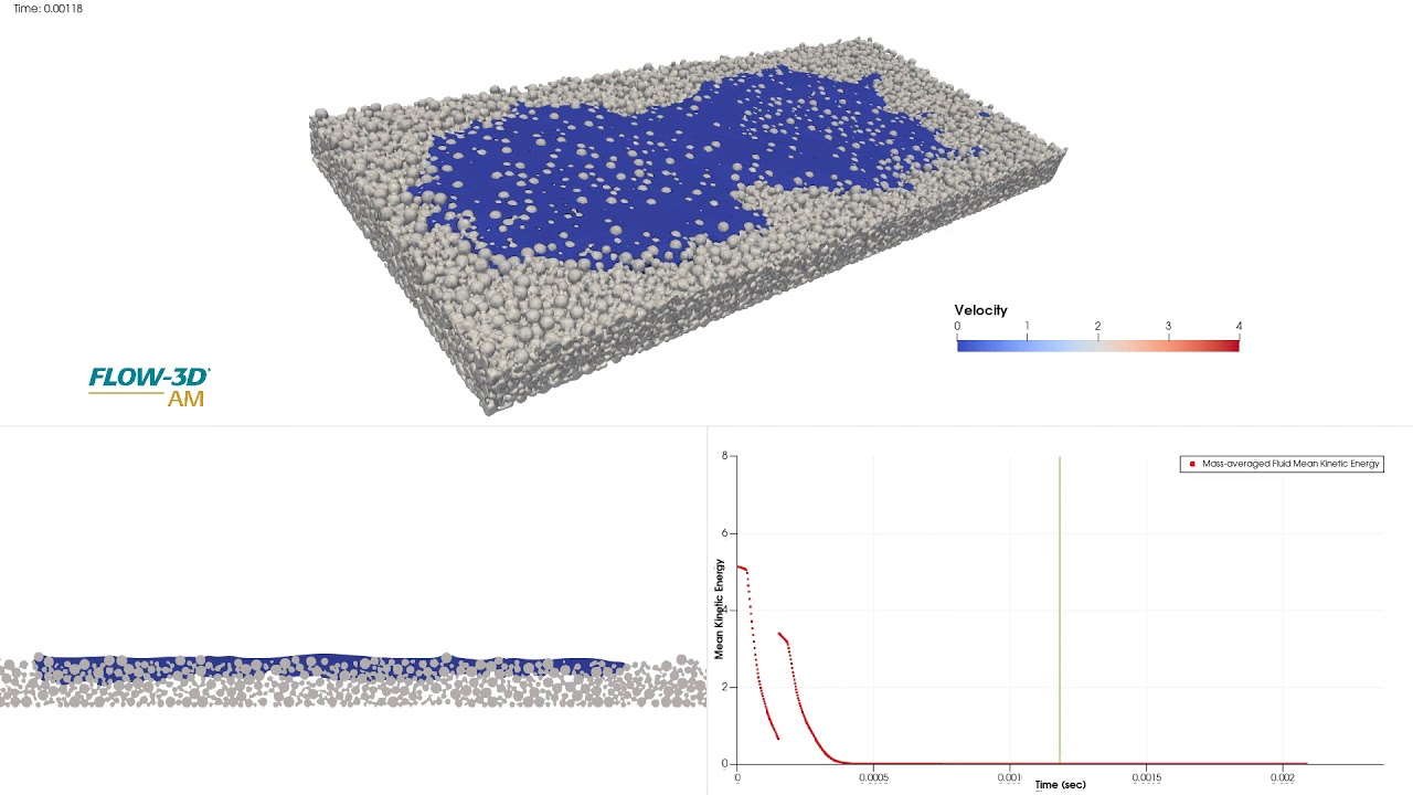
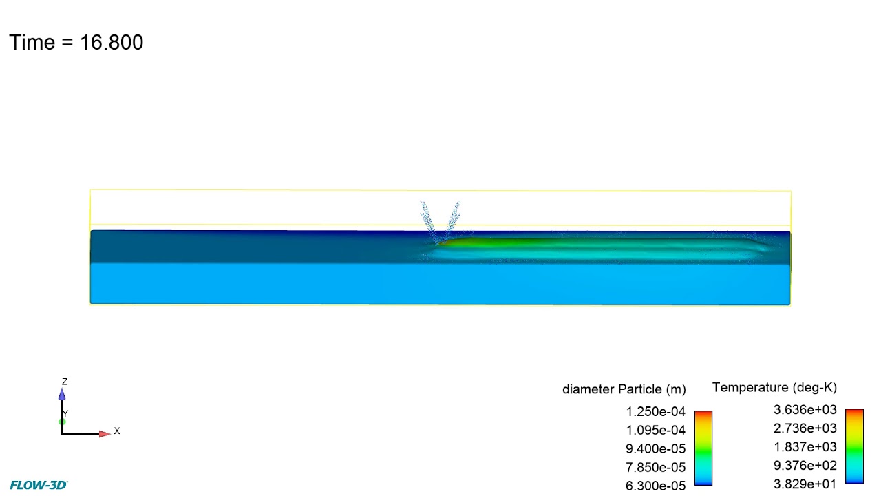
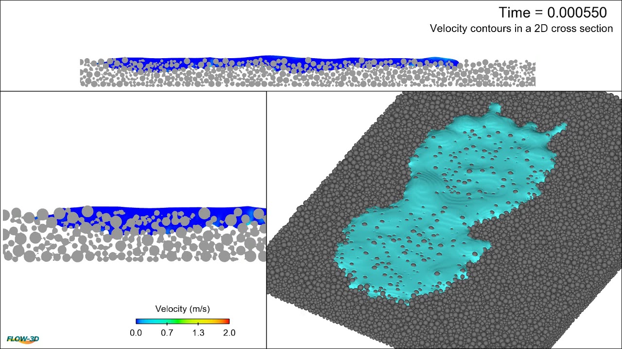
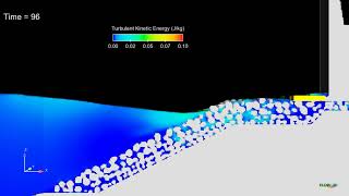
In this simulation, we look at fluid impact on a powder bed. The material properties of the fluid and the process parameters such as powder size distribution and droplet velocities influence the spreading, coalescence and penetration of the fluid into the powder bed. Capillary forces help the fluid to penetrate further into the powder bed. The mass-averaged kinetic energy plot shows that the fluid eventually reaches steady state indicating the depth of penetration and seepage into the medium. Learn more about modeling capillary action through CFD at www.flow3d.com.
FLOW-3D POST ray trace rendering of a FLOW-3D HYDRO model of an energy dissipating baffled outlet. Learn more about FLOW-3D HYDRO‘s advanced CFD modeling solution for the civil and environmental engineering industry at www.flow3d.com/hydro
Degas bottles have been extensively used in engine coolant systems in automobiles, mainly to de-aerate the coolant fluid and provide room for expansion. This FLOW-3D simulation of a Degas bottle uses the full 2-fluid model to simulate both the coolant and air phases, which are represented with fluid fractions of 1 and 0 respectively. The video shows how the coolant in the system behaves under different vehicle accelerations.
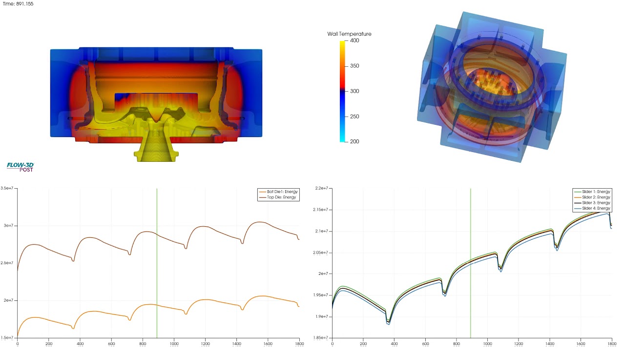
Thermal die cycling is used to heat the mold components to proper operating temperatures before starting production. Proper analysis of die thermal management protocols can inform extended die life and part quality. Simulation can be used to assess areas of heat saturation over many cycles. Additionally, once a thermal steady state has been determined, the profile can then be used to inform a filling simulation with greater accuracy.
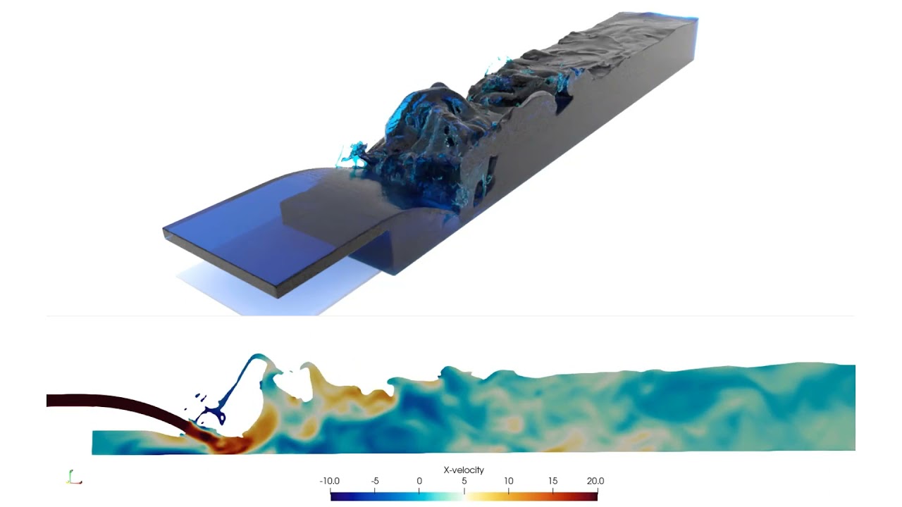
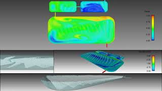
Development of a hydraulic jump simulated with FLOW-3D HYDRO. The top view is a ray-traced rendering of the flow; the bottom view, a 2D slice of the velocity field. This simulation was postprocessed with FLOW-3D POST, our new postprocessor for visualization and analysis across FLOW-3D products. Learn more at www.flow3d.com/hydro
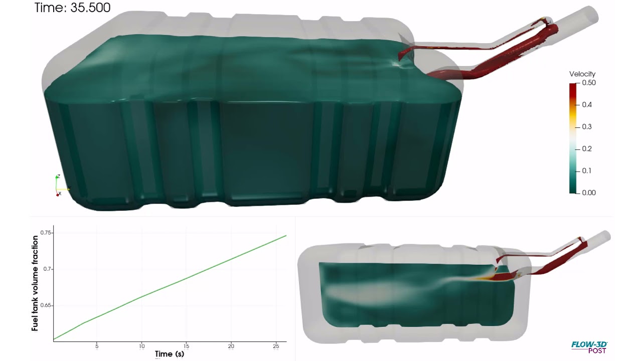
Automotive fuel tanks are designed to account for compressibility of fuel vapor while refueling and to prevent early shut-offs at fuel stations. This can cause shuddering of fuel vending units, eventually causing damage. Improper shut-offs can also cause fuel spillage or fire. Typically, fuel tank shapes are designed based on chassis or frame limitations. Shown here is a simulation of a simple fuel tank through refueling where a secondary vent tube (smaller tube on top) is simulated to allow fuel to completely fill the tank and initiate timely shutoff. This can be done either as a single and multi-fluid analysis in FLOW-3D, simulating vapor backpressure and fuel flow. The animation shows velocity contours of fuel and volume fraction of the fuel tank being filled.
With the increased availability of high performance computing platforms, large scale simulation of complex free surface flows can now include very high meshing density, which delivers for the user a very high accuracy representation of the flow. This labyrinth weir model includes the free surface flow, as well as an estimate of air entrainment.
This simulation uses FLOW-3D HYDRO‘s Moving Objects model, which couples solids with the surrounding fluid. The full mass tensor of the ship is needed to accurately characterize the hull dynamic behavior. In this side launch, the ship is released from a standby position to slide down rails before impacting the the water.
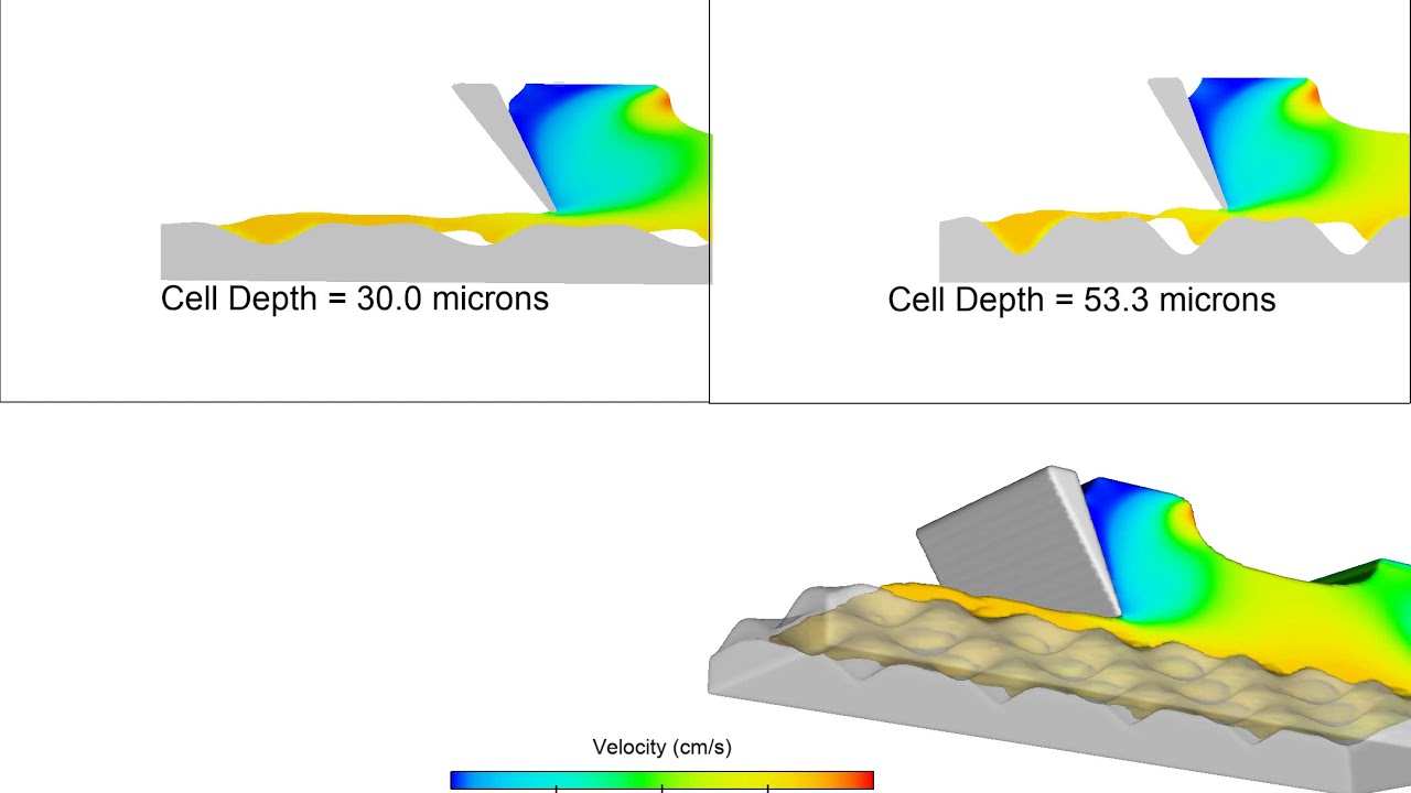
This FLOW-3D simulation of a gravure coating looks at the effect of cell depth on deposition. The model compares two cell depths: 30 microns and 53.3 microns. The 30-micron cell depth allows for a much more uniform deposition, which will transfer to the resultant coating.
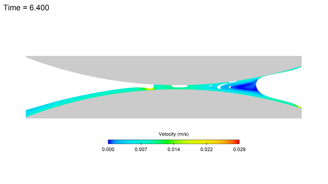
In this simulation, FLOW-3D captures a cascade defect in a forward roll coating process. Due to increased roll speed of the web roller on the top, the dynamic contact line becomes unstable which allows for air to be entrained into the coating fluid.
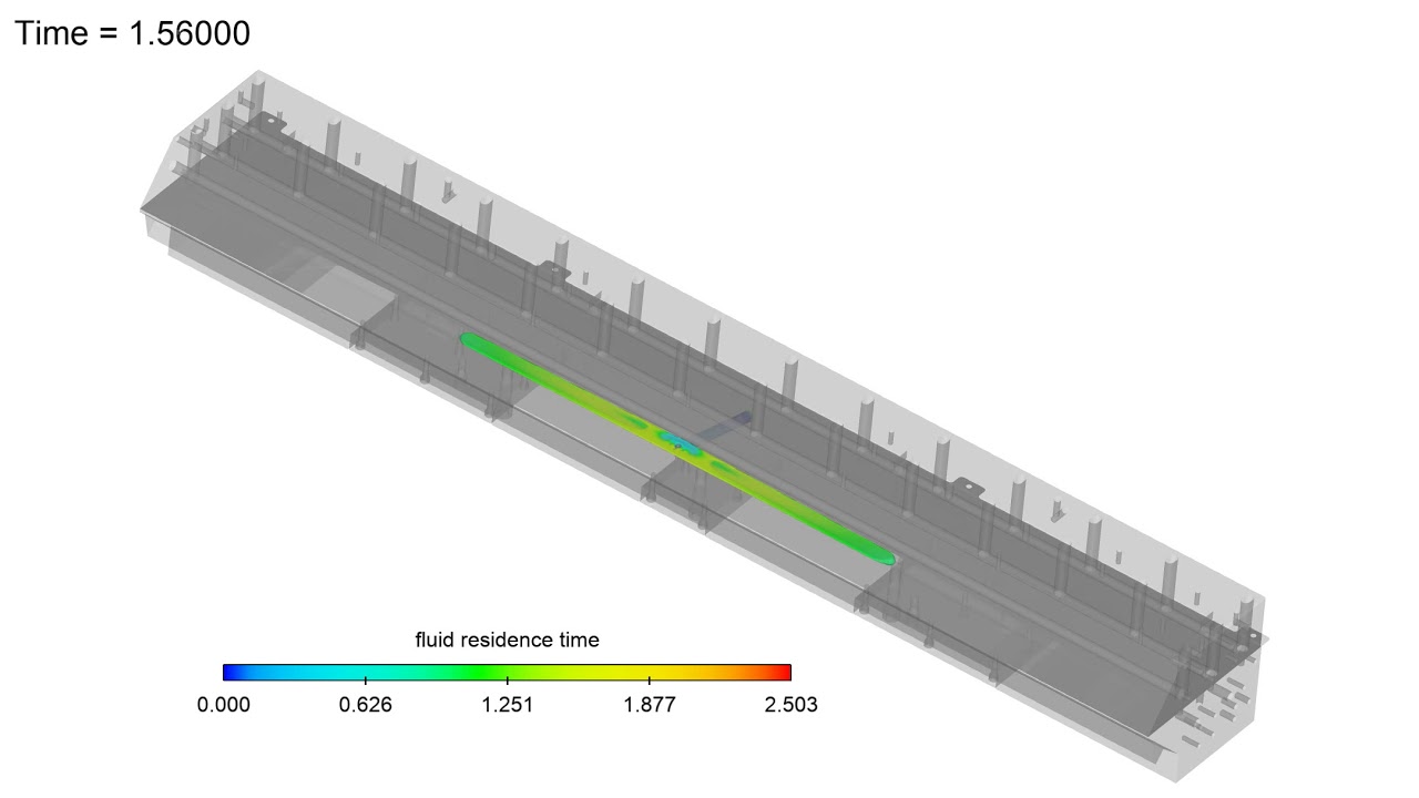
This FLOW-3D simulation, courtesy of 3M, shows the fluid residence time inside the internal cavity of a slot die. The design of the slot die is very important to the success of the coating process, and is specific to the rheology of the coating fluid.
FLOW-3D AM Playlist
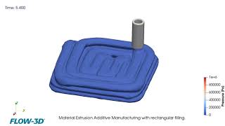


This example demonstrates FLOW-3D‘s capabilities to simulate a material extrusion AM process. In this simulation, the material is approximated as a highly viscous fluid with constant material properties. Four layers with rectangular filling are printed and the deformations of already deposited material under the newly extruded strands can be observed. The example is post-processed with FLOW-3D POST.
This example demonstrates FLOW-3D‘s capabilities for simulating a material extrusion AM process. In this simulation, a single strand of highly viscous material is extruded and deposited on a stationary substrate. The heat transfer model is activated, and the density is evaluated as a function of strand temperature after the deposition, which allows the material shrinkage to be predicted. The example is post-processed with FLOW-3D POST.
Micro and meso scale simulations using FLOW-3D AM help us understand the mixing of different materials in the melt pool and the formation of potential defects such as lack of fusion and porosity. In this simulation, the stainless steel and aluminum powders have independently-defined temperature dependent material properties that FLOW-3D AM tracks to accurately capture the melt pool dynamics.
In this FLOW-3D AM simulation of a wire/powder-based directed energy deposition process, powder particles and wire feed are melted onto a substrate by way of a laser. Tracks are laid next to and on top of eachother where they solidify to build a 3D part. This simulation can be used to study the influence of process parameters like laser power, powder injection rates, wires feed rates, scan speeds and material properties on fusion and subsequent mechanical properties.
In this FLOW-3D AM simulation of a powder-based directed energy deposition process, powder particles are melted onto a substrate by way of a laser. Tracks are laid next to and on top of each other where they solidify to build a 3D part. This simulation can be used to study the influence of process parameters like laser power, powder injection rates, scan speeds and material properties on fusion and subsequent mechanical properties.
Fused Deposition Modeling (FDM) is one of the most widely used 3D printing techniques, but not much research has been done on polymer extrusion and flow characterization. How do extrusion speeds and nozzle geometries affect the FDM process? This is a question that researchers from Technical University of Denmark tried to answer using CFD models built in FLOW-3D AM. This simulation video shows the polymer flow within the liquifier at different extrusion speeds. At speeds greater than 160 mm/min, oscillations set in and the process becomes unstable. A recirculation zone forms near the interface of the solid filament and the melt zone, which prevents the polymer melt from flowing upstream.
L-PBF processes involve complex multi-physics phenomena such as fluid flow, heat transfer, surface tension, phase change and solidification that significantly influence the process and ultimately, the build quality. FLOW-3D AM’s physical models simulate the melt pool phenomena at the meso-scale by accounting for particle size distribution and packing fractions while simultaneously solving for the mass, momentum and energy conservation equations.
This FLOW-3D AM simulation was provided by a customer, and is modeling a powder-based directed energy deposition process where powder particles are injected onto the substrate and melt under the application of a laser beam to form multiple build layers. This simulation can be used to study the influence of process parameters such as laser power, scan speed, and powder injection rates on thermal gradients, fusion between tracks and layers, and subsequent microstructure.
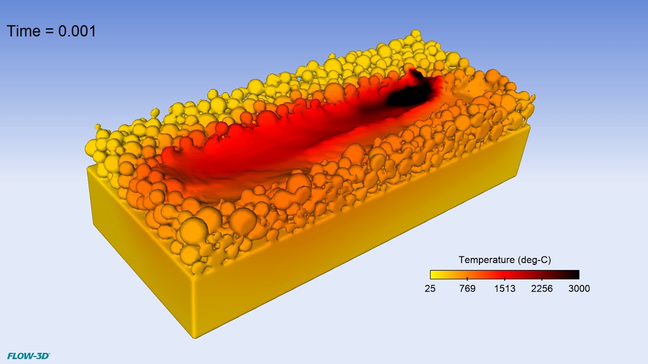
This simulation is looking at melt-pool dynamics when printing multiple layers in a laser powder bed fusion process using FLOW-3D AM. This CFD software enables researchers to run high-fidelity simulations at the melt-pool scale of both powder physics and laser-material interactions to understand the resultant fusion, thermal profiles, and solidification from depositing additional layers.
This simulation is looking at a L-PBF process in which the laser transverses the substrate in zigzag pattern. The remelting that occurs between tracks can influence the microstructure of the solidified metal, so it is important to understand how to optimize hatch spacing and scan strategy to achieve desired temperature gradients and cooling rates. FLOW-3D AM provides for melt pool scale process analysis to fine tune these influencing parameters.
Laser beam shaping is being used more in L-PBF processes for melt-pool stability which leads to better uniformity within parts. This simulation using FLOW-3D AM is looking at the effect of a multicore laser profile on process stability.
This simulation is looking at droplet ejection of a piezo driven inkjet. These drop-on-demand (DoD) printheads are used for a variety of applications from conventional printing processes to additive manufacturing processes such as binder jetting and material deposition. FLOW-3D allows for analysis of how system parameters and fluid rheology affect droplet velocities, uniformity, and overall consistency in the printed image or part.
Simulation of a multi-material extruder using pressure pulses to initiate material flow which allows for alternating material extrusion. FLOW-3D allows for analysis of the effect of the thermophysical properties of the material, heat transfer between solid and liquid, as well as solidification on process stability in material extrusion.
This simulation is looking at material extrusion and deposition from the hot end in a fused deposition modeling process. The solid polymer filament is heated and melted in the heating chamber which then flows out of the nozzle and solidifies on the moving substrate. FLOW-3D allows for analysis of the effect of the thermophysical properties of the material, heat transfer between solid and liquid, as well as solidification on process stability in material extrusion.
This simulation of powder-based laser metal deposition (LMD) demonstrates the process of depositing Fe-304 stainless steel powder concurrently with a laser source. FLOW-3D AM can be used to investigate the effect of parameters such as laser power, scan strategy, and powder injection rate on the subsequent thermal gradients, cooling rates, and fusion conditions for multiple layers.
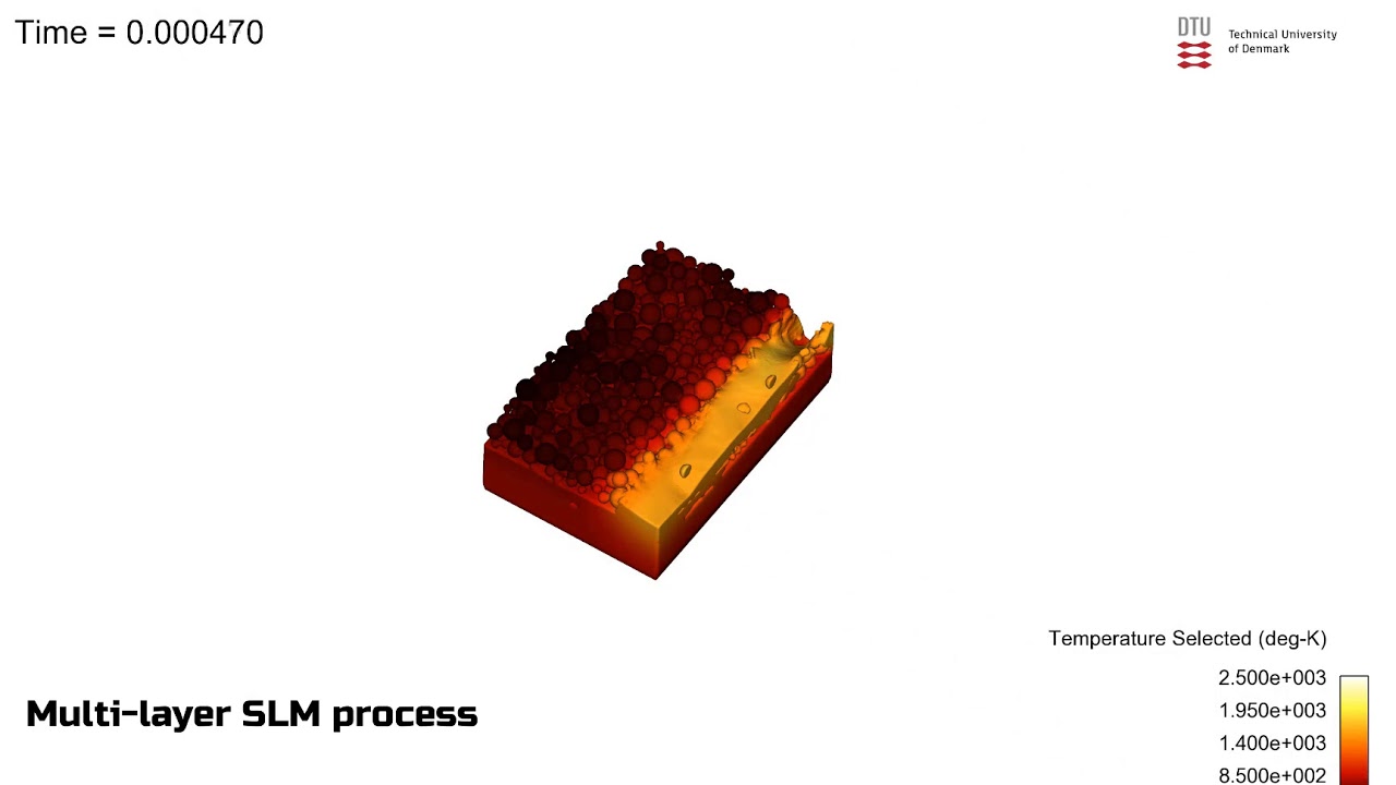
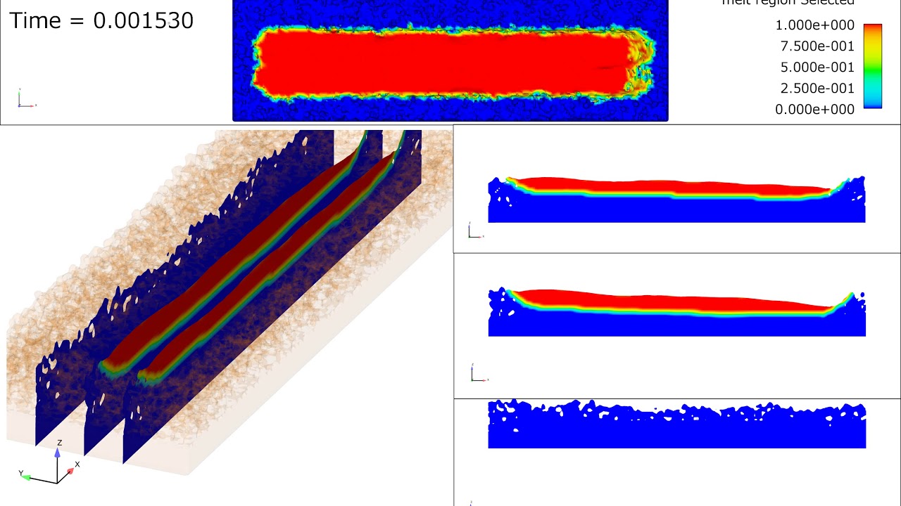
This simulation from our customers at DTU – Technical University of Denmark shows a multi-layer selective laser melting (SLM) process modeled using FLOW-3D DEM and FLOW-3D WELD. The model considers the powder compaction, fusion, and solidification between subsequent layers to analyze and optimize process parameters which impact the powder bed and melt pool dynamics.
In this FLOW-3D AM simulation of a powder-based directed energy deposition process, powder particles are injected into the domain, where they melt under the application of a laser beam and form the first build layer. This simulation can be used to study the influence of process parameters like laser power and powder injection rates, and further extended to analyze multi-layer builds.
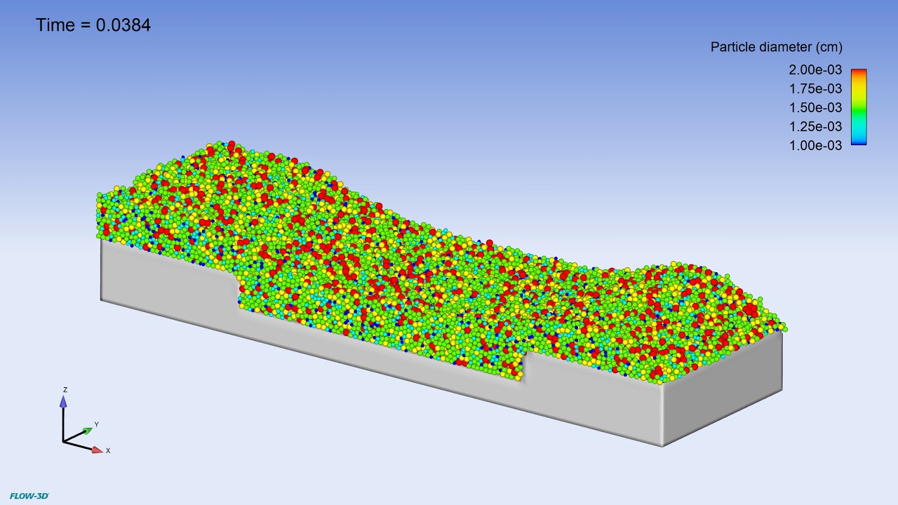
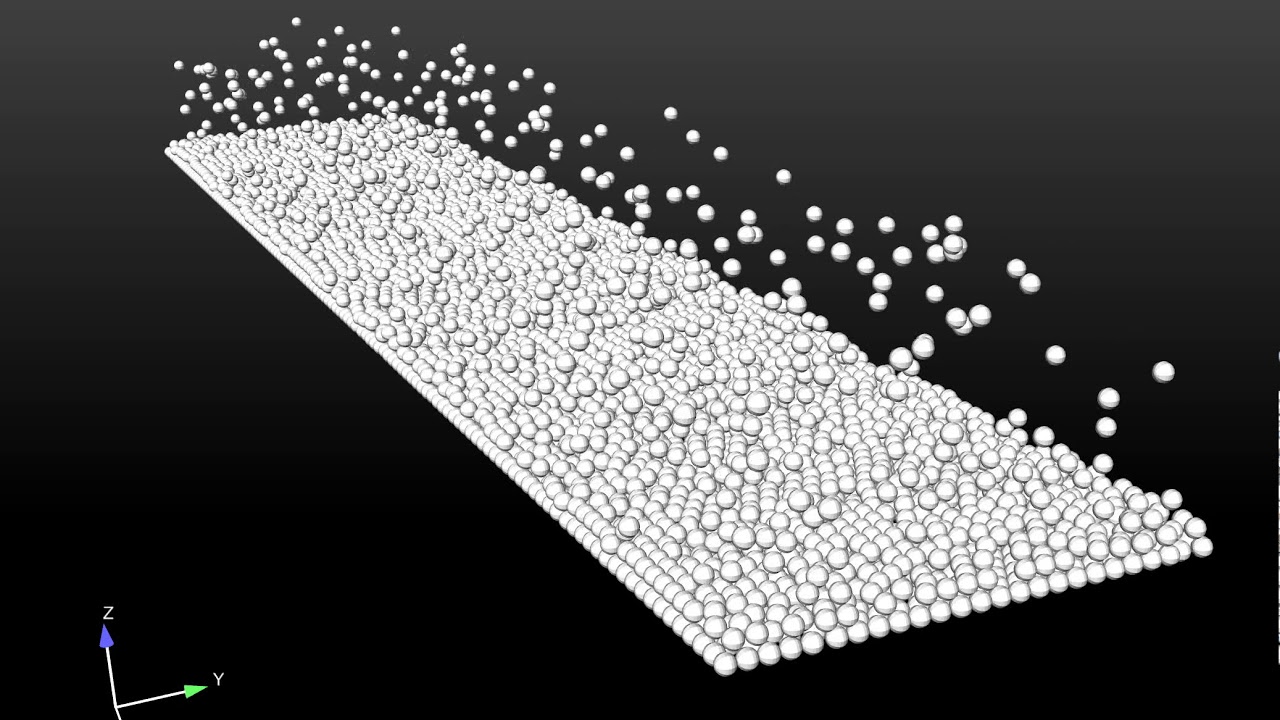
Particle spreading simulation to understand particle bed compaction for laser powder bed fusion processes. Particles vary in size from 10 to 20 microns and are made of a steel alloy. Particle dynamics are captured using the discrete element method (DEM).
Particle bed laying simulation with particles varying in size from 10 to 20 microns made of a steel alloy. Capturing particle dynamics using the discrete element method is the first step in simulating the laser power bed fusion process in FLOW-3D AM.
Melt pool level simulations using FLOW-3D AM help understand the mixing of different materials in the melt pool and the formation of potential defects such as lack of fusion and porosity. In this simulation, the powders have independent temperature dependent material properties, with FLOW-3D AM being able to accurately track the evolution of the melt pool dynamics.
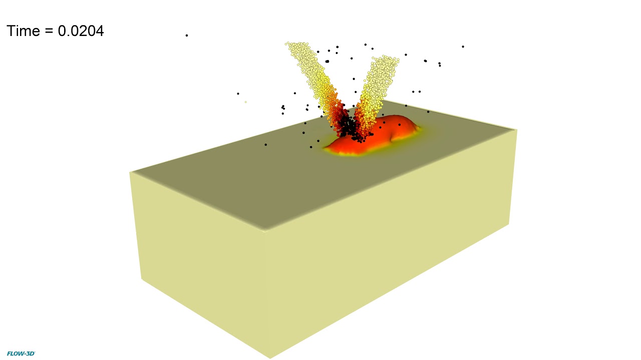
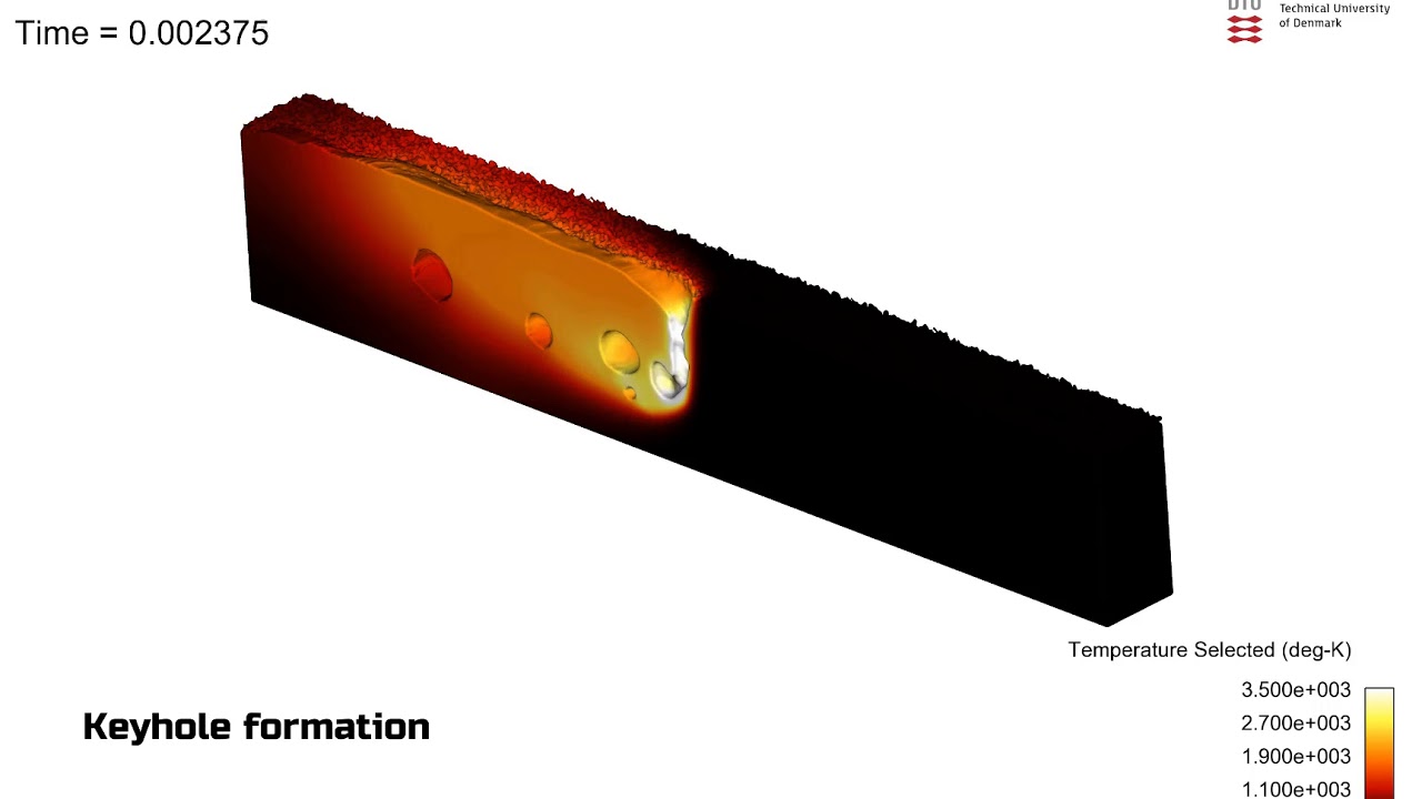
This simulation from our customers at DTU – Technical University of Denmark shows keyhole-induced porosity during laser powder bed fusion. FLOW-3D AM provides detailed, highly accurate data on how specific process parameters affect melt pool dynamics.
This simulation of a laser powder bed fusion (L-PBF) process was created using the full capabilities of FLOW-3D AM. Powder laying, spreading and compaction is simulated using FLOW-3D DEM, while FLOW-3D WELD is used to model and analyze the laser beam process parameters and their effect on the powder bed.
Wire-based laser metal deposition, or LMD-w, is a process in which parts are made by deposition of laser-melted wire, and is near-net-shape process. FLOW-3D AM is used to achieve process stability through optimization of laser power, wire speed, and wire feed orientation.
For this selective laser melting process, FLOW-3D AM is modeling the transient evolution of the melt pool whose profile can be analyzed through 2D clips of each individual track. Using FLOW-3D AM, researchers can analyze melt pool dynamics occurring at the micron scale as a function of laser physics, material properties, and the effects of surface tension, heat transfer, viscous flows, evaporation pressure, phase change, and solidification.
Moving particles sources are now available in FLOW-3D v12.0. Assigning movement to particle sources comes in handy in powder (metal particles) beam additive manufacturing simulations, where the powder beam source moves with the laser source to deposit material and heat precisely at the same location on the build. In this simulation, the powder beam source is set to move in rectangles, and so is the laser source (not visible here), to create a rectangular build.
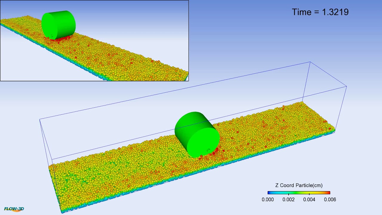
In this FLOW-3D discrete element method (DEM) simulation, a roller compacts a bed of powder particles. The model can account for particle-particle interactions as well as particle-moving object collisions. In the wake of the roller, it can be seen that the elevations of the particles decrease, once the roller passes over.
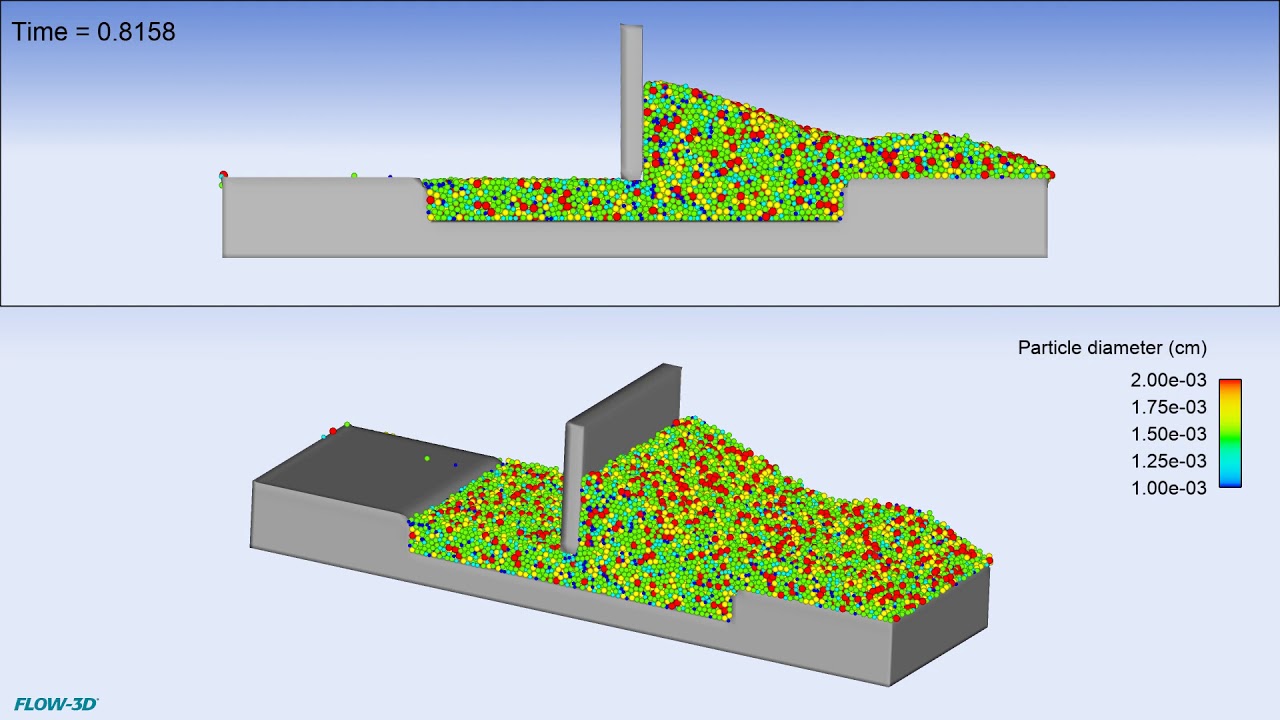
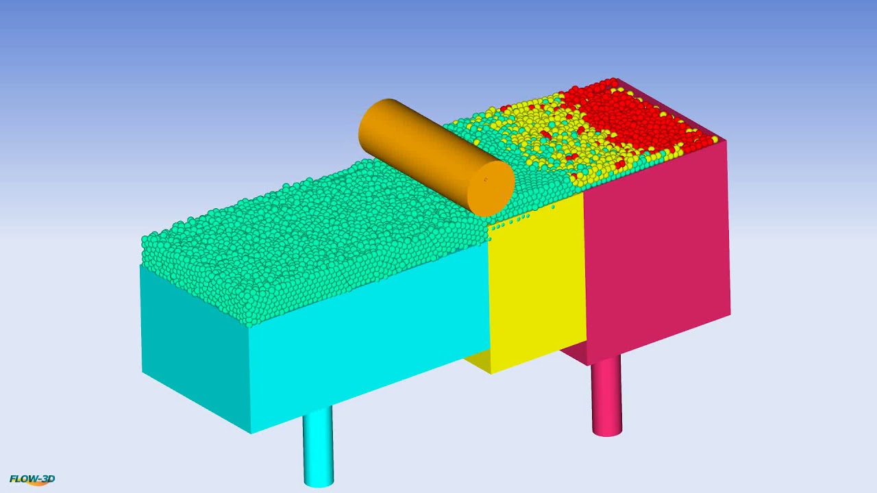
This FLOW-3D simulation uses the discrete element method (DEM) to study powder spreading due to a counter-rotating cylindrical roller. At the beginning of the video, the powder reservoir shifts down, whereas, the build platform moves upward. Immediately after, the roller spreads the powder particles, which are color-coded according to their initial location, to the build platform, in preparation for the next layer to be melted and built. Such simulations can provide additional insights into the preferred sizes of powder particles being transferred from reservoir to the build platform.
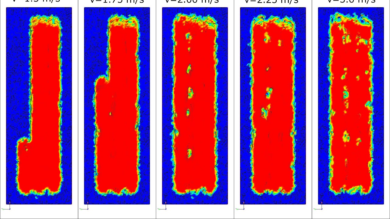
A laser powder bed fusion simulation showing the formation of melt pools in multiple laser scan tracks with varying scan speeds. At lower scan speeds there is better powder melting and fusing, whereas, for higher scan speeds, unmelted particles can be observed. The trade-off is between build speed and build quality and accordingly, appropriate scan speeds can be chosen.
A laser powder bed fusion simulation with a triangular scan strategy. Regions of interest or defects are at locations where the laser scan pattern changes direction.
Melt pool analysis of the powder bed under a laser power output of 200W, scan speed of 3.0m/s and a spot radius of 100μm.
A powder bed laying simulation where particles are dropped to simulate the natural lamination process. The material used is Ni alloy (Inconel 718) with a particle diameter of 20μm. The particle dynamics are captured using the Discrete Element Method (DEM) approach.
Binder jetting simulations provide insights into the spreading and penetration of the binder in the powder bed, which are influenced by capillary forces. Ultimately, process parameters and material properties directly influence the deposition and spreading process.
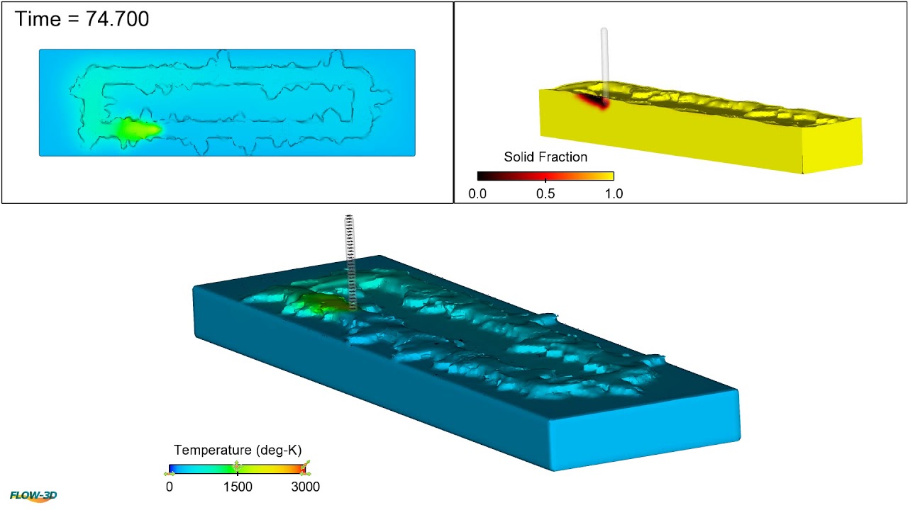
This FLOW-3D simulation shows a laser metal deposition process with multiple layer deposition. Notice the momentary pause of the particle beam motion every time the substrate changes its direction. Also, as layers are deposited, the shape of new layers changes due to the unequal addition of heat to each layer from the porous heat source.
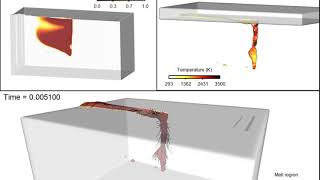
Simulation of the Direct Metal Deposition process used in additive manufacturing. A melt pool is created in the moving substrate of Inconel 718 alloy using a 1.8 kW laser, into which power of the same metal is delivered at a constant rate from three guns. The powder is simulated by the Lagrangian particle model, each 40 micron in diameter. The powder melts in the pool and eventually forms a layer of re-solidified material. The animations shows the melt pool size (top) and temperature distribution in the substrate.
FLOW-3D WELD Playlist


FLOW-3D WELD provides powerful insights into laser welding processes to achieve process optimization. With better process control it is possible to minimize porosity, heat affected zones and control microstructure evolution. To accurately simulate laser welding processes, FLOW-3D WELD implements all the relevant physics such as laser heat sources, laser-material interaction, fluid flow, heat transfer, surface tension, solidification, multiple laser reflections and phase change.
Physics such as recoil pressure, multiple laser reflections, surface tension forces and upward vapor pressure play an important role in simulating the laser keyhole welding process. In FLOW-3D WELD, it is possible to account for these physics to capture a realistic representation of the laser keyhole welding process.
This laser brazing simulation was done by researchers at GM Global R&D and Southern Methodist University using FLOW-3D WELD to understand how process parameters and laser beam inclination influenced the seam quality in laser brazing of galvanized steels.
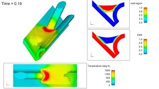
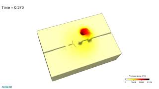
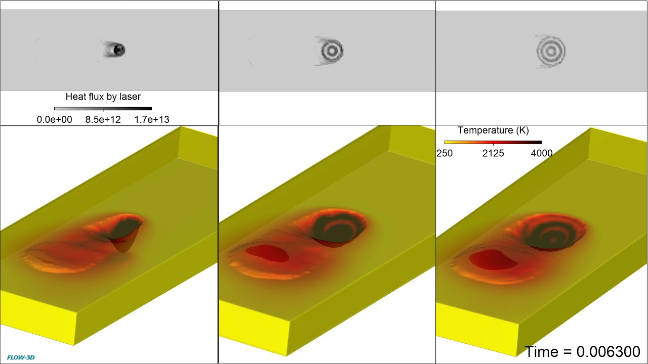
In laser keyhole welding it is important to understand the influence of the stability of the keyhole on the outcome of the weld. This simulation shows melt region as well as the void region to capture the shape of the keyhole at any instant in time. Additionally, multiple laser reflections are plotted which impact the heat transfer within the keyhole.
In this FLOW-3D WELD simulation, a low power laser is used to pre-heat components and melt a soldering wire which forms joints between two closely spaced sensitive components. FLOW-3D helps engineers understand the effects of localized heating in the soldering wire and the solid components due to the laser beam profile, and the subsequent flow and formation of the soldering joint between the two components.
Oscillation welding is a welding process in which the laser beam is rapidly rotated to help bridge gaps and make precise joints. Using FLOW-3D WELD, it is possible to simulate laser oscillation welding by accounting for oscillation frequency, beam path, substrate gap and material properties of the alloys being welded.
This video shows a laser spiral welding simulation using FLOW-3D WELD. It’s possible to input varying scan paths to simulate the joint formation in a gap welding case. FLOW-3D WELD can help with process parameter optimization of laser power and scan path to form an optimal welding joint.
In laser welding and additive manufacturing, there are different scenarios that recommend either a pulsed or continuous laser. The configuration will have a major impact on the resultant melt pool dynamics and temperature gradient throughout the part. FLOW-3D WELD can be used to compare these two configurations in order to make an informed decision for which will be optimal for any given process.
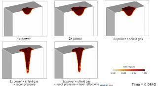
Accounting for all the relevant physics in a laser welding simulation is crucial to understanding your process. This series of FLOW-3D WELD simulations illustrates this. In the top three simulations, increasing laser power from 1x to 2x shows a conduction mode weld with increasing melt pool size and depth. The addition of shield gas pressure (top right) shows an even greater increase in the size and depth of the melt pool. The bottom two simulations illustrate a keyhole mode weld, showing the effects of vaporization, recoil pressure, and laser reflections on the weld profile.
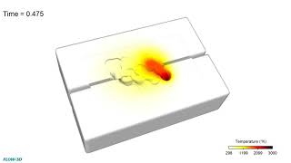
FLOW-3D WELD is used to understand the effect of laser power on fusion and porosity formation. The spot weld simulation on the left shows high input energy which leads to greater fusion, but also void formation; the simulation on the right shows a lower input energy leading to decreased fusion and no porosity.
Wire-based laser metal deposition, or LMD-w, is a process in which parts are made by deposition of laser-melted wire, and is near-net-shape process. FLOW-3D AM is used to achieve process stability through optimization of laser power, wire speed, and wire feed orientation.
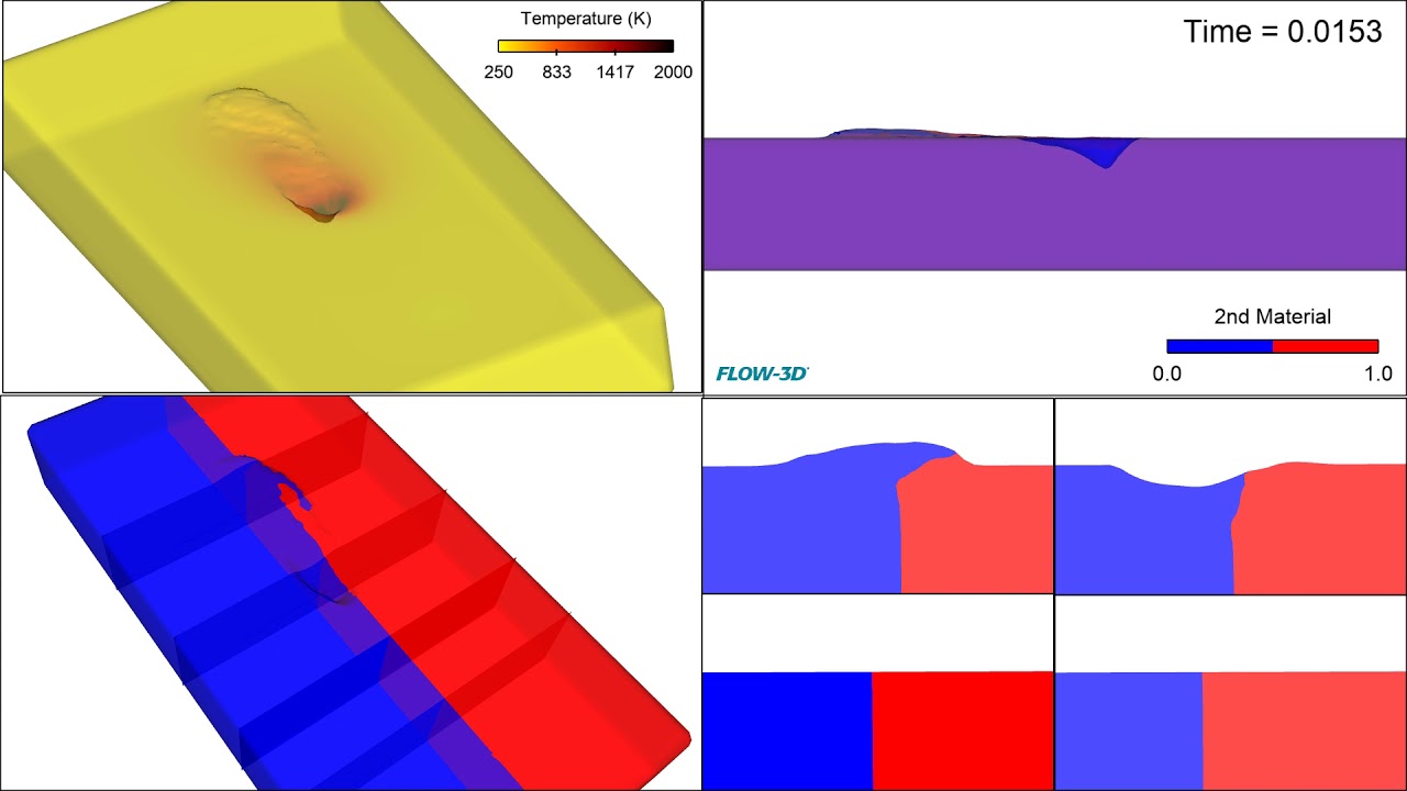
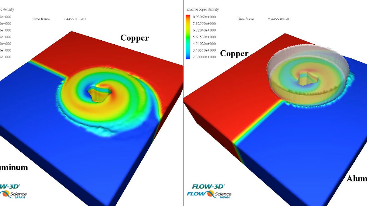
This dissimilar laser welding simulation is looking at fusion between Al and Cu alloys which are commonly used materials in battery and electronics manufacturing. Joining dissimilar metals can be challenging due to the difference in thermophysical properties and simulation can help to understand melt-pool dynamics when working with different alloys.
FLOW-3D WELD allows for arbitrary beam shaping, allowing users to analyze the effect of different beam profiles on melt pool stability, surface finish, fusion, and porosity. The simulation on the left with the smallest beam radius produces a larger depression in the melt pool, while the simulation on the right has a more stable melt pool profile.
In this FLOW-3D AM simulation of a powder-based directed energy deposition process, powder particles are injected into the domain, where they melt under the application of a laser beam and form the first build layer. This simulation can be used to study the influence of process parameters like laser power and powder injection rates, and further extended to analyze multi-layer builds.
In laser welding, the method of oscillation is useful when working with varying gap distances and faying interfaces and allows for better control of weld bead dimensions. This simulation is a direct representation of the experimental techniques used for oscillation welding.
In laser keyhole welding it is important to understand the influence of the stability of the keyhole on the outcome of the weld. This simulation shows melt region as well as the void region to capture the shape of the keyhole at any instant in time. Additionally, multiple laser reflections are plotted which impact the heat transfer within the keyhole.
This simulation done using FLOW-3D WELD is looking at friction stir welding of aluminum and copper alloys. Simulation is used to understand the surface melting pattern as well as to calculate Von Mises stresses to determine if the material will yield or fracture.
FLOW-3D WELD simulations looking at different oscillation welding techniques used to bridge gap distances.
Laser welding involves multitude of physics and skipping any of those may cause significant change in the final melt pool profile. FLOW-3D WELD is capable of incorporating high level of complex physics required to fully simulate a melt pool caused by a laser. The video shows the evolution of deep penetration (using high power laser) melt pool under different levels of physics complexities. Top left: Deep penetration only, Top right: Deep penetration with shield gas, Bottom left: Deep Penetration with shield gas and evaporation pressure, Bottom right: Deep penetration with shield gas, evaporation pressure and Fresnel reflections.
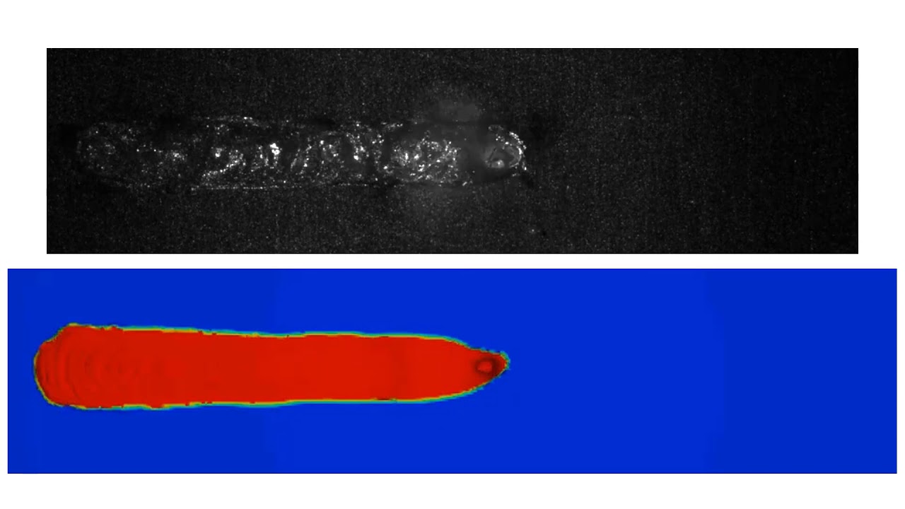
A deep penetration laser welding simulation that results in two melt pools at the top and bottom surfaces. Such stress tests are carried out to calibrate the simulation models with actual experimental observations.
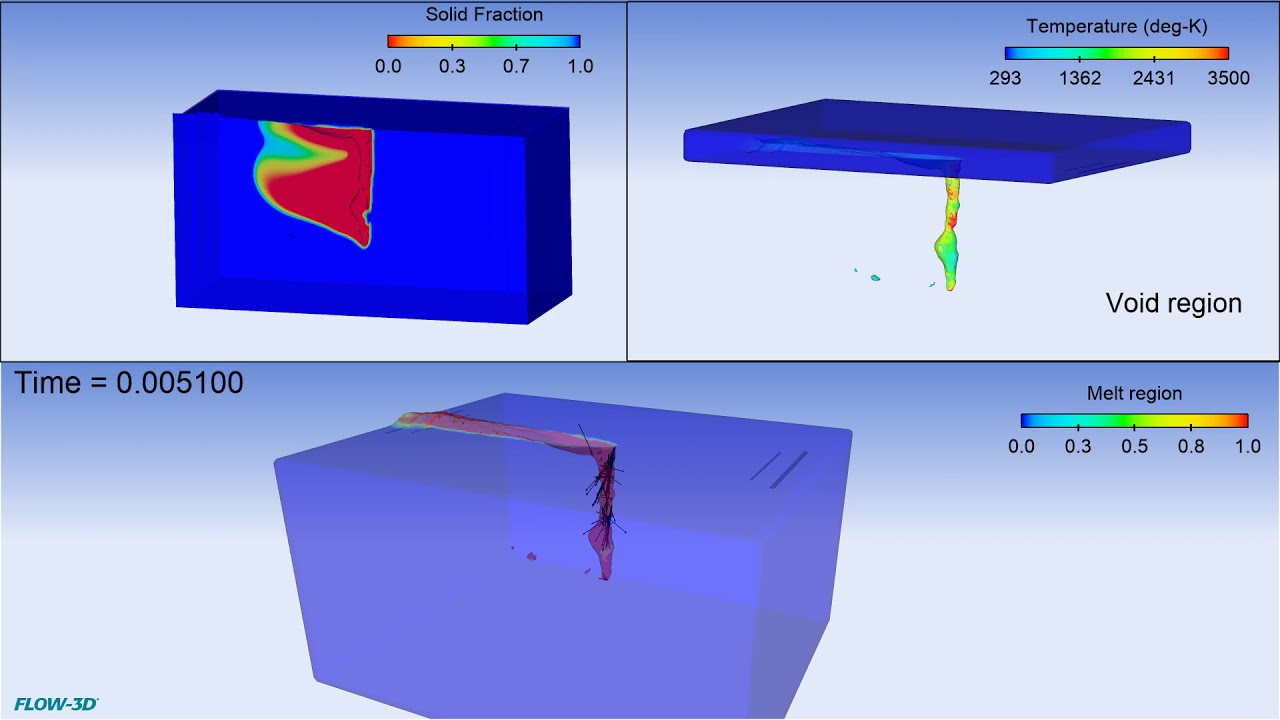
A laser welding simulation showing the formation of voids and their subsequent entrapment in the melt pool. When the advancing solidification front captures these voids, it results in porosity.
A CFD simulation showing the laser welding of two metal plates offset at the top and bottom surfaces. The laser power is sufficiently high to penetrate through the metal plates completely and create melt pools at the top and bottom surfaces that helps achieve complete fusing.
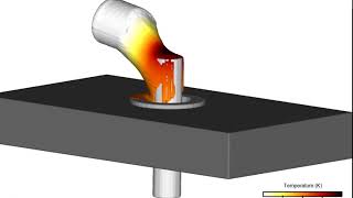
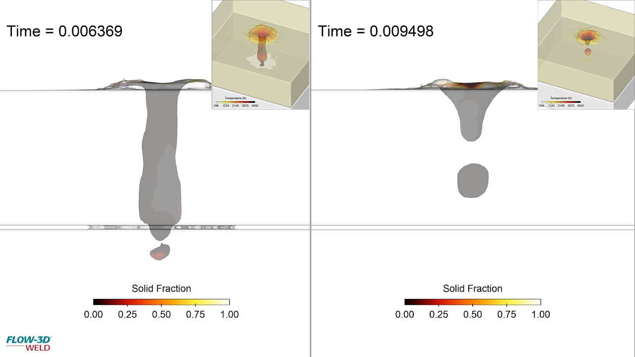
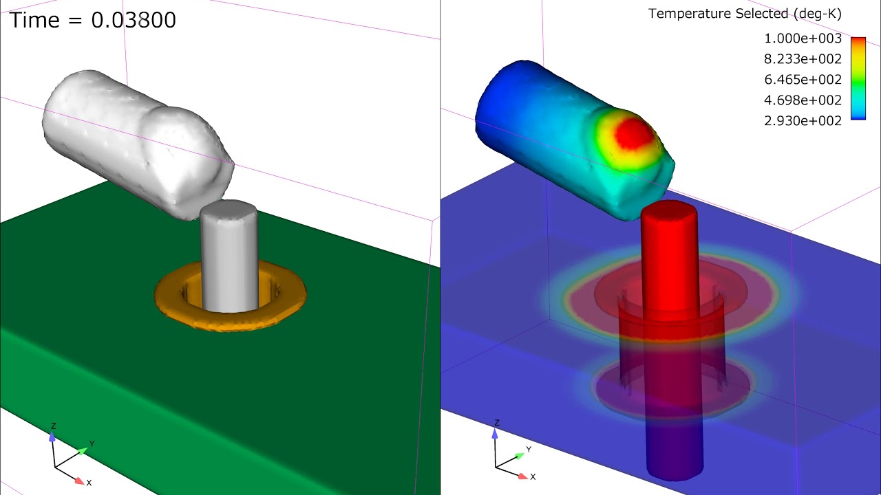
Animation of the drop welding case simulated in FLOW-3D that uses the two-fluid, two-temperature approach instead of the two-fluid, one-temperature approach. With the two-fluid, two-temperature approach, the metal drop retains its initial temperature leading to more realistic simulation results.
In this FLOW-3D WELD simulation, a low power laser is used to pre-heat components and melt a soldering wire which forms joints between two closely spaced sensitive components. FLOW-3D helps engineers understand the effects of localized heating in the soldering wire and the solid components due to the laser beam profile, and the subsequent flow and formation of the soldering joint between the two components.
Laser brazing uses a filler metal to join two or more close-fitting parts without melting the base material. Laser brazing is ideal for achieving a strong, smooth-surfaced weld between joint surfaces that may not be of the same material. FLOW-3D WELD provides valuable insights into the process design parameters that affect the quality and stability of the weld.
Simulation of the Direct Metal Deposition process used in additive manufacturing. A melt pool is created in the moving substrate of Inconel 718 alloy using a 1.8 kW laser, into which power of the same metal is delivered at a constant rate from three guns. The powder is simulated by the Lagrangian particle model, each 40 micron in diameter. The powder melts in the pool and eventually forms a layer of re-solidified material. The animations shows the melt pool size (top) and temperature distribution in the substrate.
This FLOW-3D simulation shows a laser metal deposition process with multiple layer deposition. Notice the momentary pause of the particle beam motion every time the substrate changes its direction. Also, as layers are deposited, the shape of new layers changes due to the unequal addition of heat to each layer from the porous heat source.
FLOW-3D HYDRO Playlist


The accuracy and robustness of the sharp-interface tracking VOF methods in FLOW-3D have been enhanced by combing them with fluid particles. The new particle species, called VOF particles, are used in place of the VOF function to track small fluid ligaments and droplets in the computational domain, achieving better conservation of fluid volume and momentum.
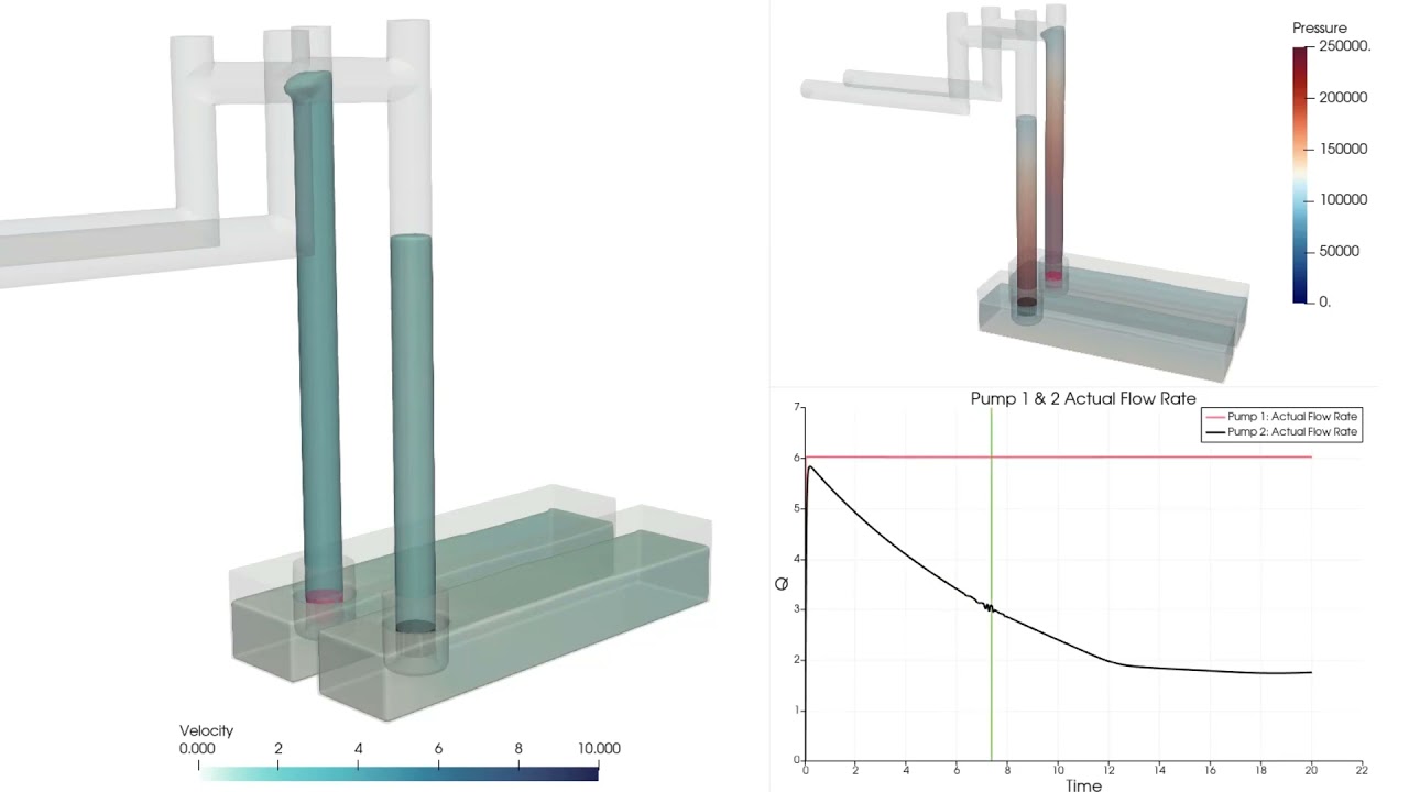
FLOW-3D’s new axial pump model allows users to mimic the net effect of an axial pump in their simulations. There are two options with respect to the pump behavior. The first option is to prescribe either a volumetric flow rate or a flow velocity through the pump so that the fluid is moved at the specified rate. This option is appropriate when an operating flow rate is provided for the pump. The second option provides a more complete definition of the pump operation based on a pump performance curve.
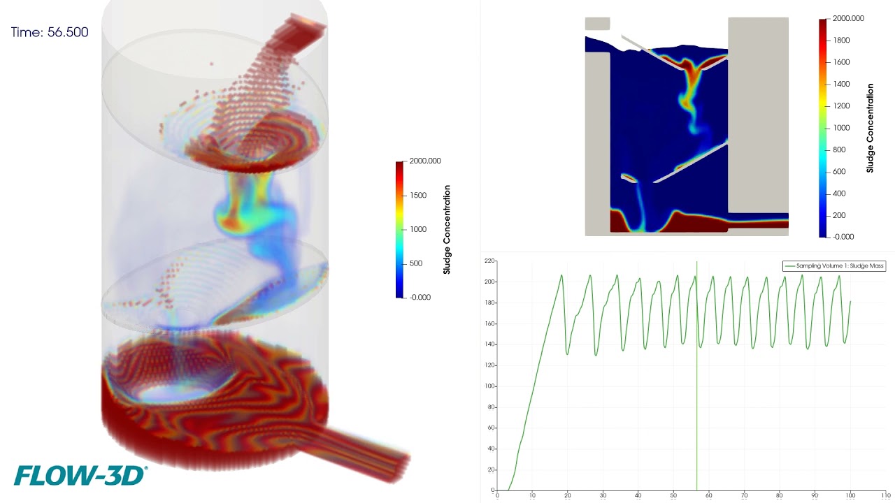
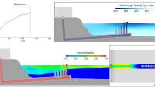
This example represents a sludge decanter that models a mixture of water and sludge entering a decanter and separating. Water is allowed to flow in and out at the back side of the decanter to maintain a relatively fixed level in the decanter. A sampling volume in the bottom of the decanter is used to measure the amount of sludge captured at the bottom. When the sludge mass in the sampling volume reaches 200 kg, a valve opens to release the sludge. The valve closes when the sludge mass drops below 180 kg.
In this simulation, oxygen bubbles are injected from two diffusers at the bottom of the container and allowed to rise in water. As the bubbles rise, oxygen dissolves into water. The image on the left shows the concentration of dissolved oxygen in water. The image on the right shows the water velocity which is induced by the rising oxygen bubbles.
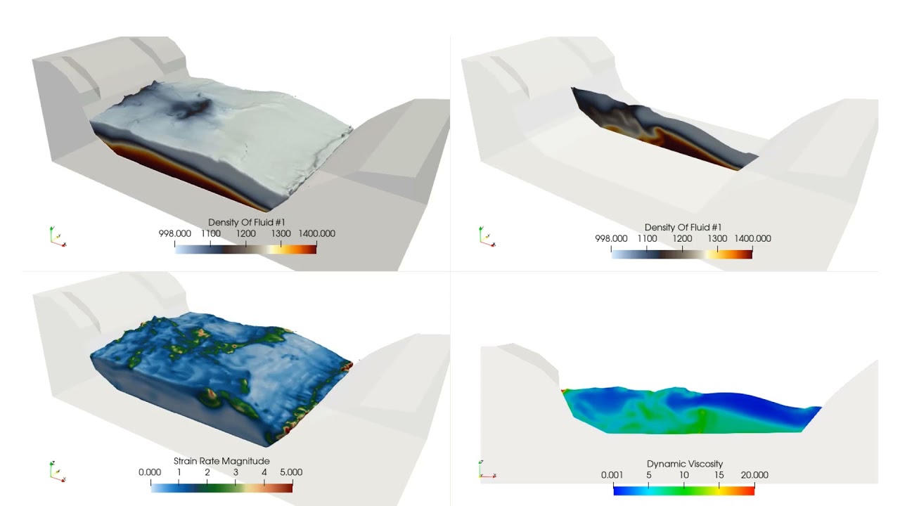
Viscosity is defined as a function of both solid content (density) and strain rate. In this example a dense fluid region slides down into a quiescent pool which at time zero is layered with a dense settled fluid region and clear water above.
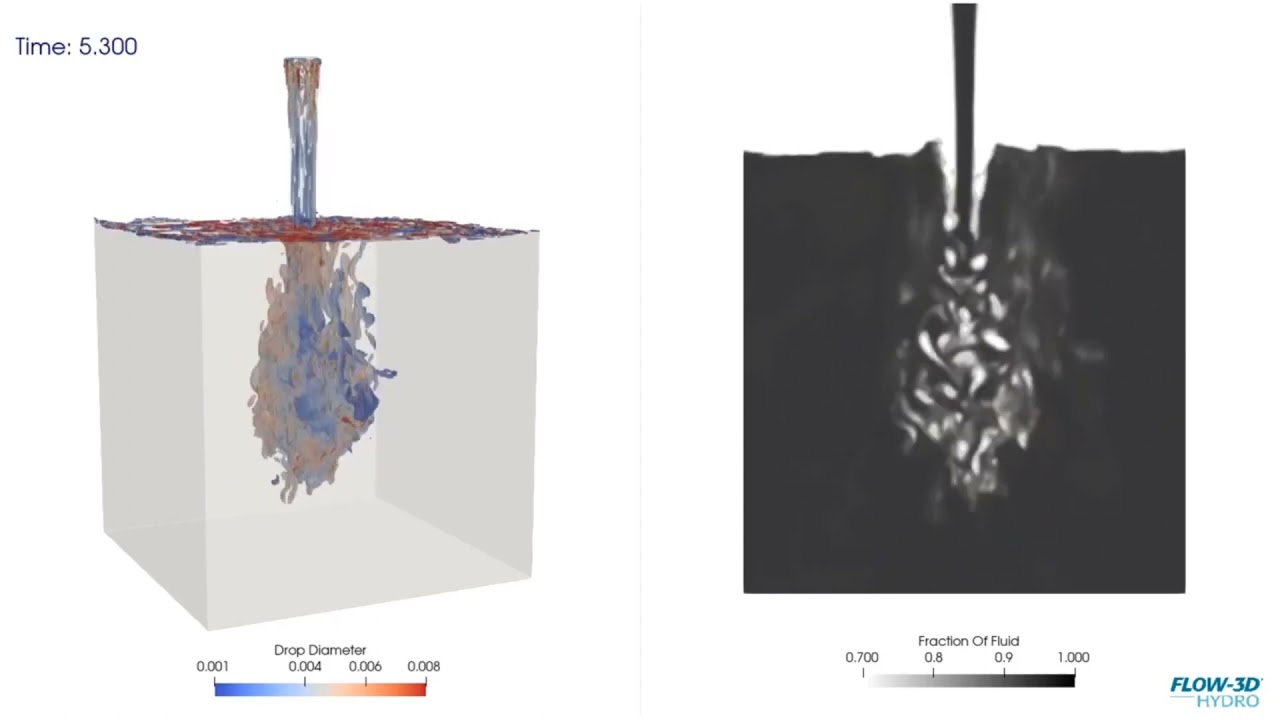
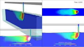
In this simulation of air entrainment at a free surface due to a vertical impinging jet, inclusions of air at the free surface jet contact are entrained into the bulk of the body of water after which they will rise or may also be entrained along with ambient flow. FLOW-3D HYDRO offers different methods to model this process. This particular model uses a 2 phase VOF with LES turbulence, although 1 phase VOF with the air entrainment model in FLOW-3D HYDRO is more commonly used.
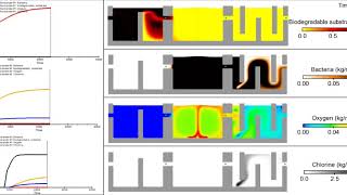
Disinfection of water is an important part of wastewater/water treatment processes. One method of disinfection uses chlorine added to the water in a Contact Tank. This simulation models the interactions between chlorine and a pathogen in a contact tank. The simulation first models the hydrodynamics of the contact tank. Then the disinfection process is modelled using a scalar model to represent the chlorine and pathogen and is coupled with a reaction kinetics model to model the consumption of the chlorine and the decay of the pathogen due to disinfection.
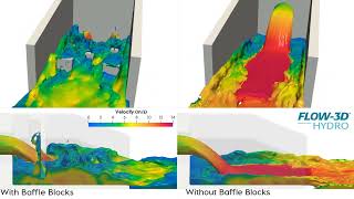
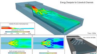
This FLOW-3D HYDRO simulation compares the velocities of a culvert outlet with baffle blocks and without. Both models have the same flow exiting the culvert outlet.
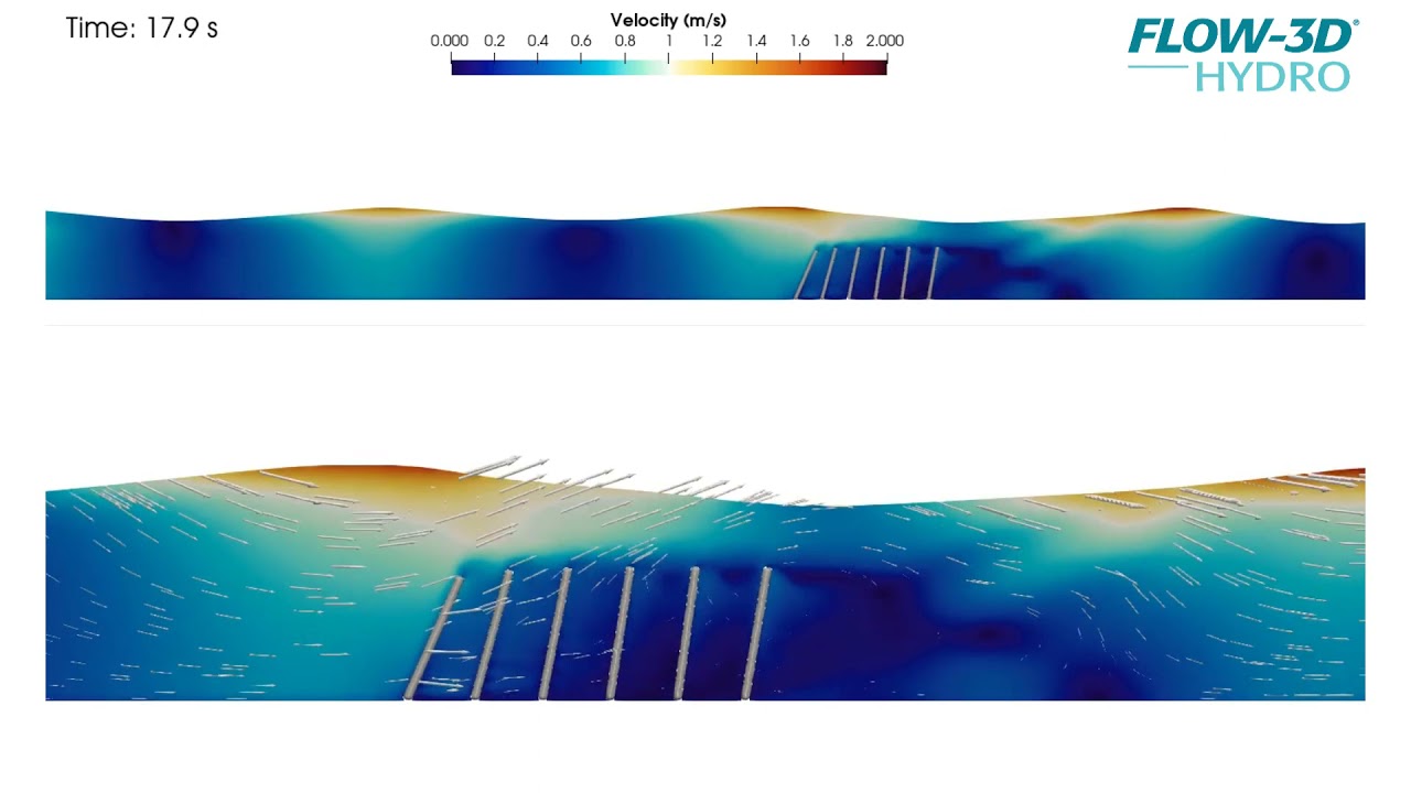
A FLOW-3D HYDRO model of waves passing over a series of simple moving objects represents flow through a submerged, flexible coastal canopy.
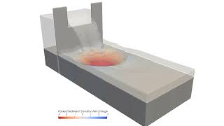
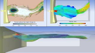
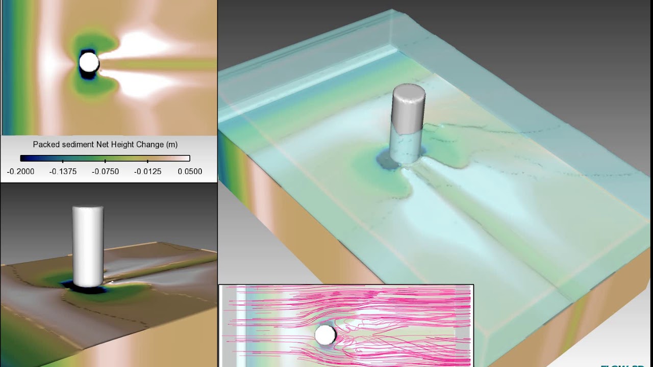
Save time, avoid mistakes, and run consistent models with FLOW-3D HYDRO’s Workspace Templates. Workspace Templates pre-load fluid properties, physical models, numerical settings and simulation outputs for common applications, including sediment transport. The sediment transport model in FLOW-3D HYDRO can be used to evaluate scour and deposition, where three-dimensional flow components are driving the scouring process.
This FLOW-3D HYDRO CFD simulation uses the Hybrid 3d/Shallow Water model to better understand and more efficiently model bridge hydraulics. The simulation fully couples the 3D model with a 2D shallow water model together in one run. The surrounding areas to the bridge were modelled in full 3D, while the upstream and downstream areas of the river were modelled using a 2D shallow water model.
This FLOW-3D HYDRO simulation shows a scalar concentration of a neutrally buoyant plume modeled using the Large Eddy Simulation (LES) turbulence model.
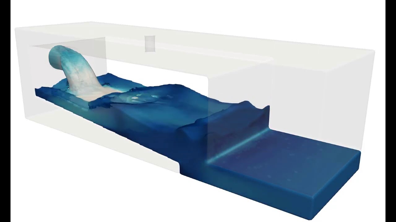
Hydraulic jumps such as the one shown in this simulation can be engineered to provide energy dissipation at dam outfalls and other structures which would be at risk due to the kinetic energy of the flow. This simulation was created in FLOW-3D HYDRO and post-processed using FLOW-3D POST‘s ray tracing capabilities.
Development of a hydraulic jump simulated with FLOW-3D HYDRO. The top view is a ray-traced rendering of the flow; the bottom view, a 2D slice of the velocity field. This simulation was postprocessed with FLOW-3D POST, our new postprocessor for visualization and analysis across FLOW-3D products.
Rendering of a FLOW-3D HYDRO dense jet simulation, this visualization uses volume thresholds in FLOW-3D POST, Flow Science’s new postprocessor available across all FLOW-3D products.
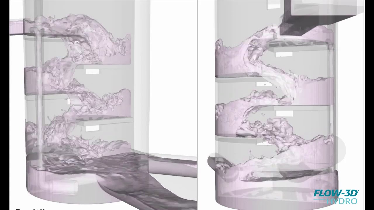
Baffle drop shafts transport storm water to underground tunnels for storage and transport. FLOW-3D HYDRO can be used to compare drop shaft design elements such as shaft diameter and baffle spacing, which affect the flow velocity, amount of entrained air entrained, and other flow features.
FLOW-3D POST ray trace rendering of a FLOW-3D HYDRO model of an energy dissipating baffled outlet.
Under certain flow conditions tangential dropshaft are effective by promoting the formation of a vortex core in the dropshaft as the flow is propagated to lower elevations. FLOW-3D HYDRO offers multiple modeling approaches to help engineers model free surface flow characteristics, and evaluate the energy dissipation, downdraft and air entrainment behaviors of the system.
This pre-packaged FLOW-3D HYDRO example uses the Free surface – TruVOF template available in FLOW-3D HYDRO for users to quickly setup common free surface hydraulic models. Water properties and all the appropriate models and numerical settings are pre-loaded into the simulation, providing a great starting point to model this vertical slot fishway from setup through to post-processing analysis.
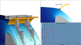
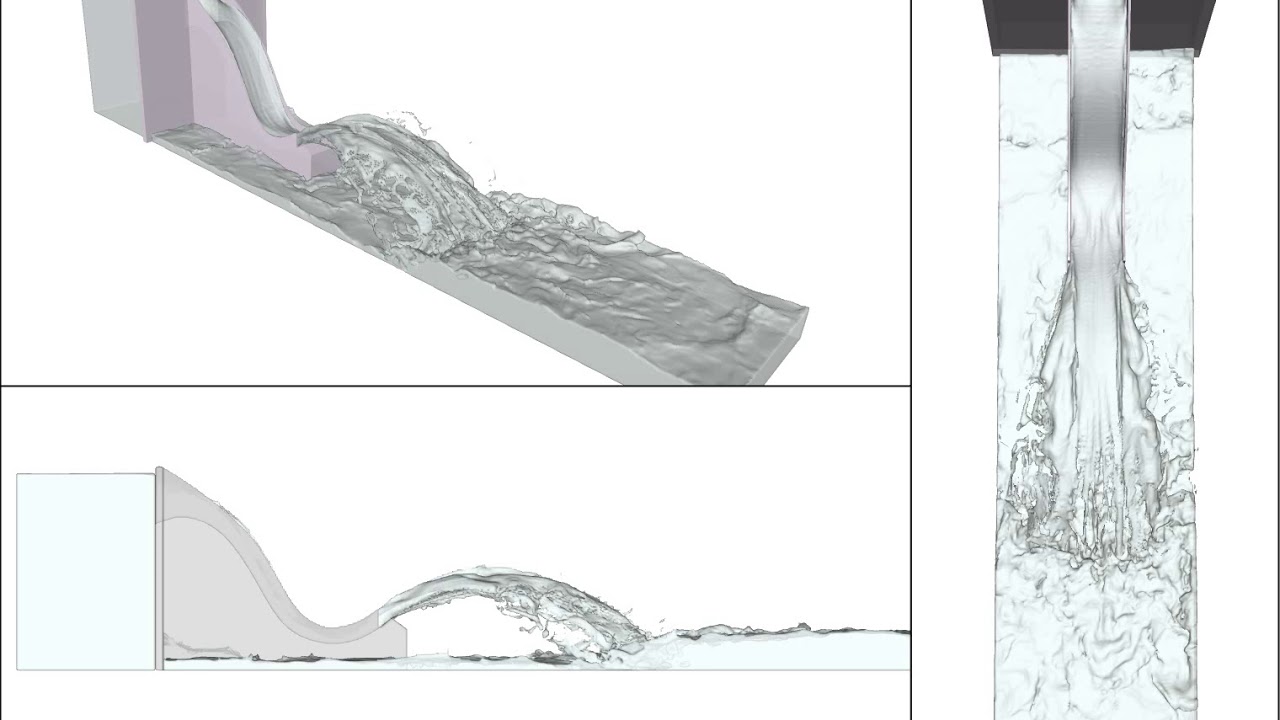
In this example of a self-priming siphon spillway, water flowing through the chute entrains so as to progressively create sub-atmospheric conditions in the siphon. In this example, the Free surface – TruVOF workspace template as well as a second order momentum advection scheme accurately captures the strongly rotational features of the flow.
Culvert capacity and bridge overtopping: as the upstream flow rate increases, the culvert may become pressurized, resulting in a complex hydraulic control made up of a culvert coupled with an overtopping weir flow.
This pre-packaged FLOW-3D HYDRO example of a discharge into a tank uses the Free surface – 2 fluid VOF template available in FLOW-3D HYDRO for users to quickly setup two phase air/water models. Air and water properties, and all the appropriate models and numerical settings are pre-loaded into the simulation, providing a great starting point to model two phase flows, from setup through to post-processing analysis.
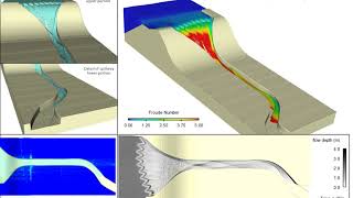
Staircase spillways can develop strong surface turbulence and self-aeration characteristics as the boundary layer progresses from the spillway’s surface up to the flow’s free surface. This FLOW-3D HYDRO example uses an LES model for turbulence modeling, as well as a second order momentum advection scheme to accurately capture the strongly rotational features of the flow within the step inner regions.
Tangential drop structures can be modeled using a two-phase 2 fluid VOF approach, or can also be modeled using a one-phase TruVOF solution combined with an air entrainment and dispersed phase modeling strategy. This 3D example uses FLOW-3D HYDRO’s Air Entrainment workspace template, as well as a second order momentum advection scheme to accurately capture the strongly rotational features of the flow within drop structure.
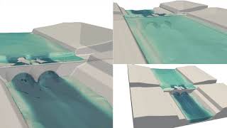
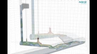
FLOW-3D HYDRO example of flow in a baffle drop structure: advanced free surface modeling capabilities deliver an extraordinarily accurate representation of the flow, even in very complex conditions like those found in a drop structure. Courtesy NEORSD, Wade Trim, and IIHR.
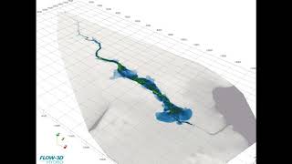
In this example of a dam breach inundation, the flow is modeled using FLOW-3D HYDRO‘s shallow water model.
Tailings breach simulation using FLOW-3D HYDRO‘s tailings model. Variable density layers including water at the very top each have their own rheological properties.
This simulation shows the turbulent intensity and volume of entrained air caused by a vertical jet plunging into a moving cross stream. The air entrainment and transport process actually involves three separate models that work together: the air entrainment model, variable density model, and drift flux models are used to approximate the air entrained at the free surface as well as the motion of the entrained air within the fluid.
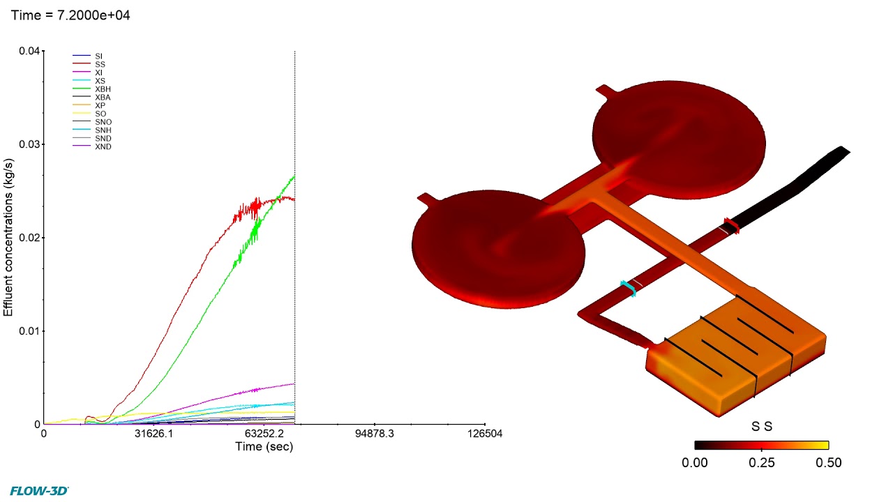
This simulation shows the water treatment process in a chlorine contact tank. Probes are used to measure the concentration of bacteria, oxygen, chlorine, and a biodegradable substrate at three points along the flow of water through the tank. FLOW-3D simulation can be used to test the design of a contact tank to ensure enough residence time for proper disinfection and avoid regions where water is allowed to remain in the tank for too long.
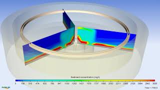
This simulation shows sedimentation in a circular clarifier. 2D clips are used to show the profiles of sludge settling at the bottom of the tank. The separation and removal of solids from wastewater through settling tanks like this one is often part of the activated sludge process, following aeration.
Aeration is part of the activated sludge process in wastewater treatment. Air is pumped into the wastewater, allowing aerobic bacteria to digest organic matter and form a floc layer before the wastewater is sent to a clarifying tank. FLOW-3D HYDRO‘s advanced auxiliary models allow water treatment modelers to go beyond the hydraulics of the flow. Grit removal, chlorine contact tanks, sludge settling and aeration all have their own dedicated models and give the user full flexibility into choosing the level of sophistication of their modeling effort.
FLOW-3D HYDRO is the ideal tool for the design and analysis of fish passage structures. Highly accurate 3D simulations of complex free surface conditions provide advanced investigations of upstream passage success through the evaluation of flow velocities, depths, drop heights and turbulence characteristics along potential movement pathways. In this simulation, the flow velocities and pattern are analyzed in a culvert with spoiler baffles.
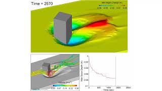
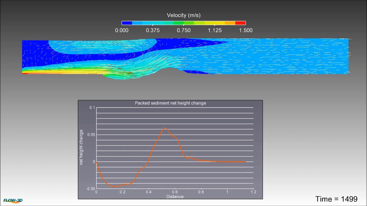
FLOW-3D HYDRO‘s sediment transport model can be used to evaluate scour and deposition, where three-dimensional flow components are driving the scouring process. FLOW-3D HYDRO’s hydrodynamic model solves the full unsteady non-hydrostatic Reynolds-averaged Navier-Stokes equations that describe the flow physics. All empirical relationships used in bedload, entrainment and settling processes are fully customizable, and up to 10 different sediment species can be defined.
Spillway plunge pools can cause significant sediment scour, which can lead to dangerous conditions at the foot of the dam and undermine the stability of the adjacent slopes. CFD simulations such as the one shown in this video can be used to analyze velocity, air entrainment, tailwater elevation and other spillway characteristics to mitigate sediment scour and other issues in dam safety.
Energy dissipating structures such as the baffles shown in this simulation can be used in some culverts and open channels to limit acceleration of the flow through the channel and help minimize downstream erosion.
Marine outfalls discharge untreated or primary treated flows into a submarine environment. Depending on its makeup, discharge can be either positive, negative or neutrally buoyant, which can affect its dispersion rate. This simulation shows the dispersion of a positively buoyant discharge plume as it exits the outfall.
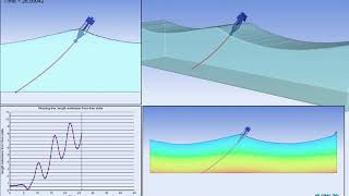
In this simulation using the moving object model, we can see how wave action affects the position of a coupled-motion floating object — in this case, a moored buoy — and the extension of its single mooring line. FLOW-3D HYDRO can be used to determine the mooring line tension and extension, as well as the overall displacement of the floating structure. Material properties of the mooring lines can be defined for spring coefficient, linear density, and drag coefficients.
FLOW-3D HYDRO can be used in the design analysis of submerged and emerged rubble-mound breakwaters to evaluate wave run-up, reflection, and hydrodynamic forces under different structural and environmental conditions.
In this simulation of a diversion tank, the moving objects model is used to simulate the opening of a sluice gate, which helps regulate the flow of storm water in a combined sewer overflow (CSO) system.
This simulation uses FLOW-3D HYDRO‘s Moving Objects model, which couples solids with the surrounding fluid. The full mass tensor of the ship is needed to accurately characterize the hull dynamic behavior. In this side launch, the ship is released from a standby position to slide down rails before impacting the the water.
FLOW-3D is an industry leader in free-surface flow modeling and is used by dam professionals to address a wide range of design problems for existing and proposed projects. Dam safety professionals and design engineers around the world rely on the efficiency and accuracy of FLOW-3D to easily generate discharge rating curves for complex spillways and control structures. With our advanced free surface modeling capabilities, FLOW-3D HYDRO can be used to simulate flow over a variety of weir shapes and gate-controlled structures.
FLOW-3D HYDRO is an industry leader in free-surface flow modeling and is used by dam professionals to address a wide range of design problems for existing and proposed projects. Dam safety professionals and design engineers around the world rely on the efficiency and accuracy of FLOW-3D HYDRO to easily generate discharge rating curves for complex spillway and control structures. With our advanced free surface modeling capabilities, FLOW-3D HYDRO can be used to simulate flow through complex geometries such as the non-linear weir shown in this example.
FLOW-3D HYDRO simulation results of flow over a weir in a river.
Accurately tracking the species and hydrodynamics calculations can equip wastewater treatment professionals to take quantitatively backed design and operations decisions.
This high definition FLOW-3D HYDRO simulation shows the flow over a flip bucket structure, a common configuration in a side channel spillway.
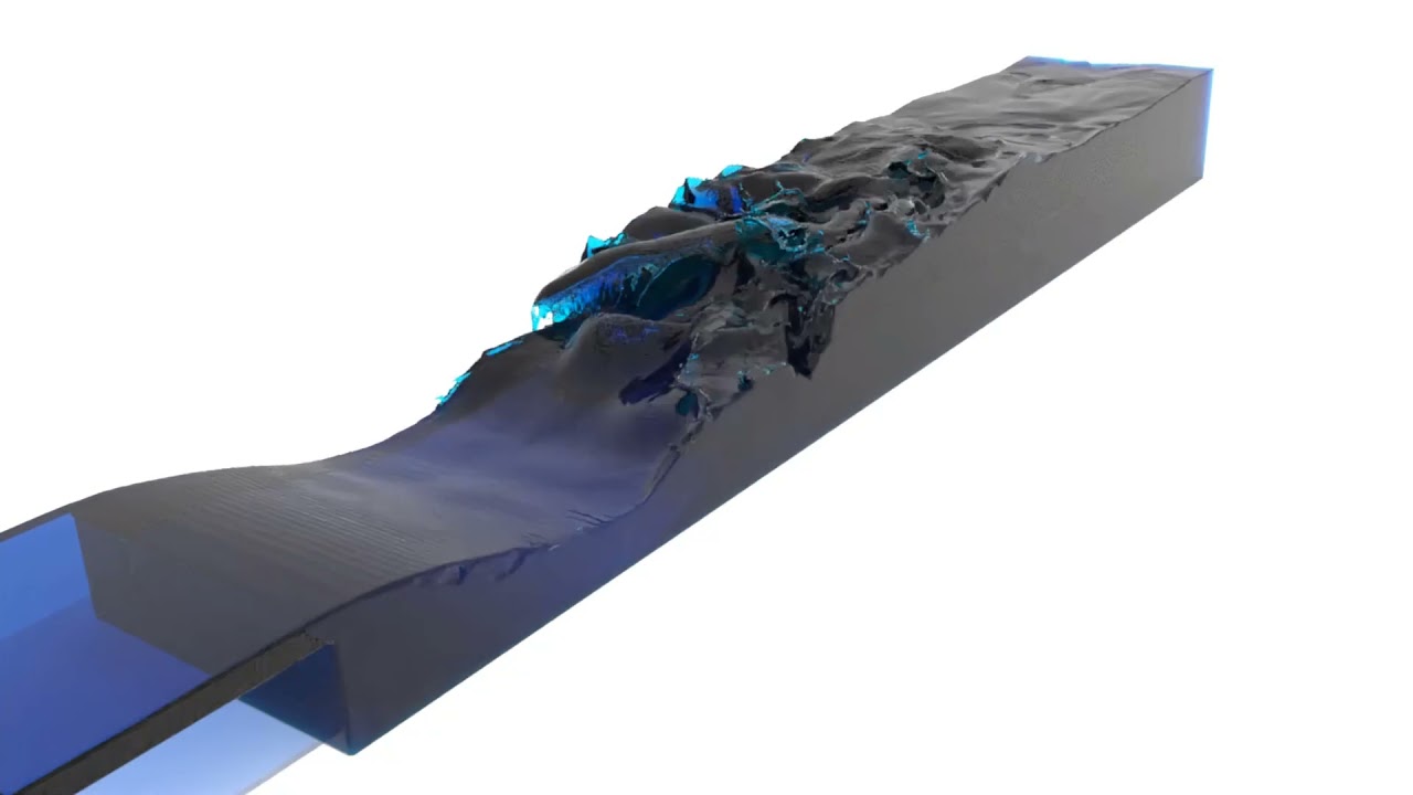
This FLOW-3D HYDRO simulation shows sediment scour formation and a dune formation for a 2D case. The FLOW-3D HYDRO results are validated against the Chatterjee experiments.
This FLOW-3D HYDRO simulation predicts scour formation around the pier in a flowing river.
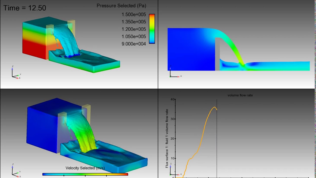
In this FLOW-3D HYDRO simulation of a flow over a sharp-crested weir, our state-of-the-art postprocessor was used to illustrate the flow velocity and pressure at the free surface and the flow velocity in a 2D slice (top right). The addition of a flux surface to the model allows the user to report the volume flow rate over time.
Metal Casting Playlist
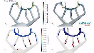
Entrained air & gas pressure within improvised HPDC runner above shot sleeve radius | FLOW-3D CAST
0:26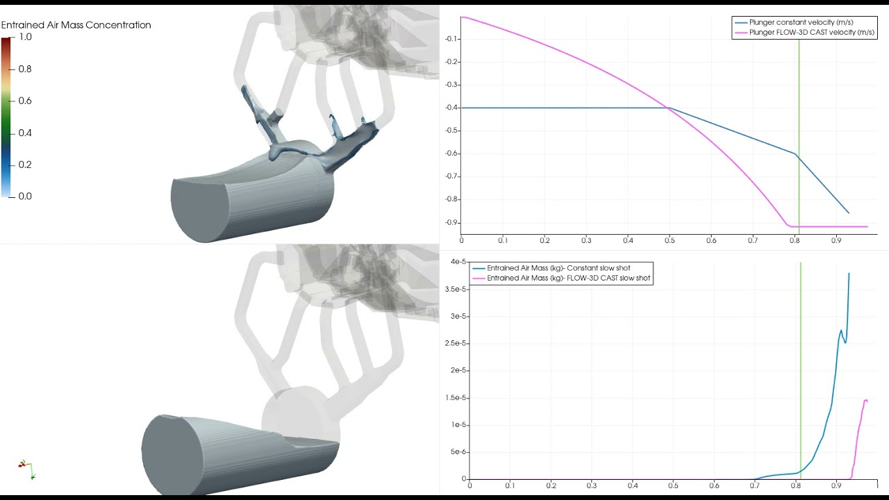
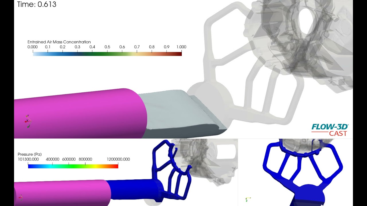
Comparison of slow shot profiles and entrained air during a HPDC filling simulation |FLOW-3D CAST
0:44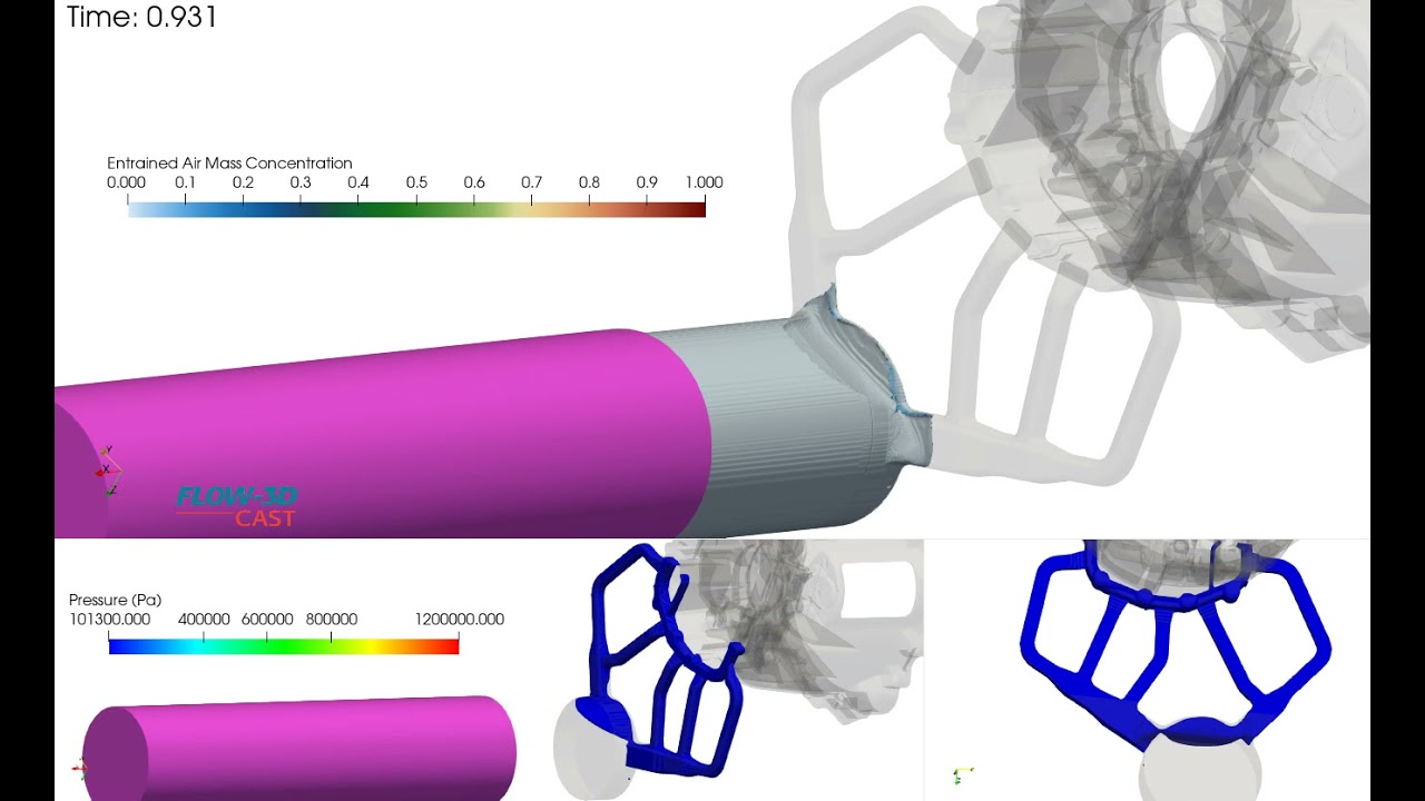


This video demonstrates Active Simulation Control being used to increase data output frequency when fast shot begins so that flow details can be captured. Flux surfaces are placed at the gates to measure the average velocity. When the average velocity exceeds 35 m/s, Active Simulation Control sets the output frequency to 0.0007 seconds for the duration of the simulation.
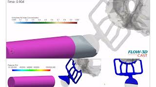
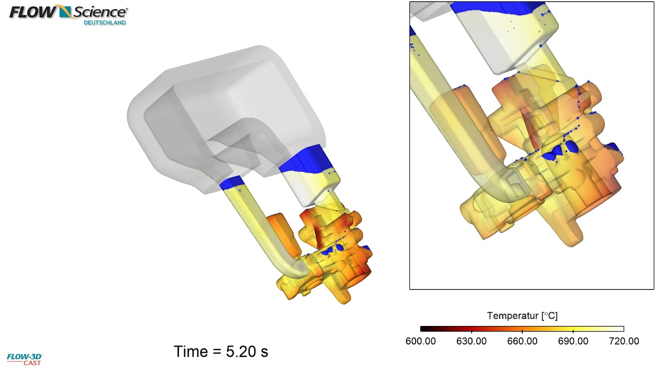
This simulation illustrates how bad runner design leads to excessive air entrained in runner, premature fill of the bell housing cavity and potential mistimed transient/fast shot. FLOW-3D CAST can help you determine the cause of problems in your casting design and how to improve it before costly mistakes happen.
This simulation shows a comparison of two high pressure die casting runner designs originating at different points off the biscuit. The video shows air mass concentration and air pressure bubbles within the runner.
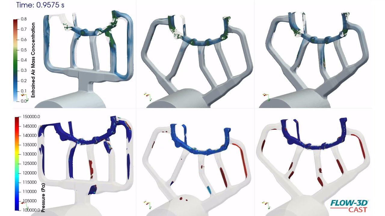
Three runner designs are compared during a high pressure die casting slow shot of a bell housing simulation. Air mass concentration and air pressure bubble color scales indicate progressive design improvement, from runner on left to runner on farthest right, with respect to runner air entrainment.
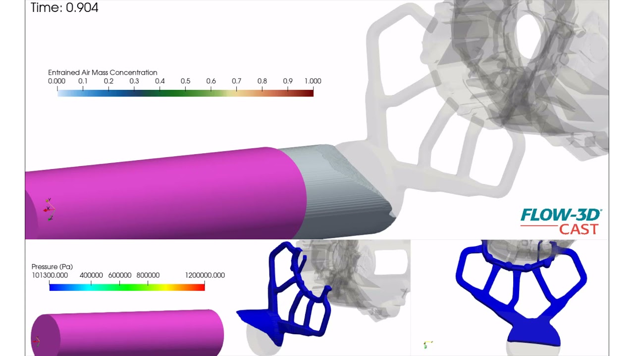
This simulation shows a high pressure die casting runner design originating above the biscuit, entraining relatively less air. The video shows air mass concentration and air pressure bubbles during slow shot of a bell housing fill simulation.
This FLOW-3D CAST HPDC simulation compares two slow shot profiles. The graphs highlight the shot profiles through time and the difference in entrained air between the slow shots. Note the lack of air entrained in shot sleeve with calculated shot profile which yields a much better controlled flow within the shot sleeve.
This FLOW-3D CAST simulation describes a calculated controlled slow shot profile entraining less air. There is minimal wave topping and disturbance to flow in shot sleeve. Some air is entrained near biscuit and through runner, however much less in comparison to constant speed slow shot profile. The video shows air mass concentration and air pressure bubbles during slow shot.
This FLOW-3D CAST HPDC simulation highlights a constant velocity slow shot with multiple stages that result in unwanted air bubbles within shot sleeve. These bubbles are transferred through runner into the casting. Notice how the metal wave laps over and topples in shot sleeve, entraining a lot of air that moves through runner before fast shot. Also, the momentum of metal is different in runner as air bubbles influence metal volume and path in runner, irrespective of runner design. Some of this air can likely be forced out of the casting through intensification pressure, but it is highly undesirable and can be avoided with a better shot profile acceleration input. The video shows entrained air mass concentration colored over metal volume and air pressure (open regions), while air bubbles are entrained in slow shot.
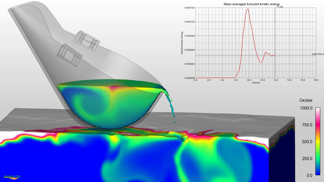
FLOW-3D CAST allows the user to model and compare ladle shape, ladle motion with 6 degrees of freedom, surface oxide formation and transfer into the ladle pour.
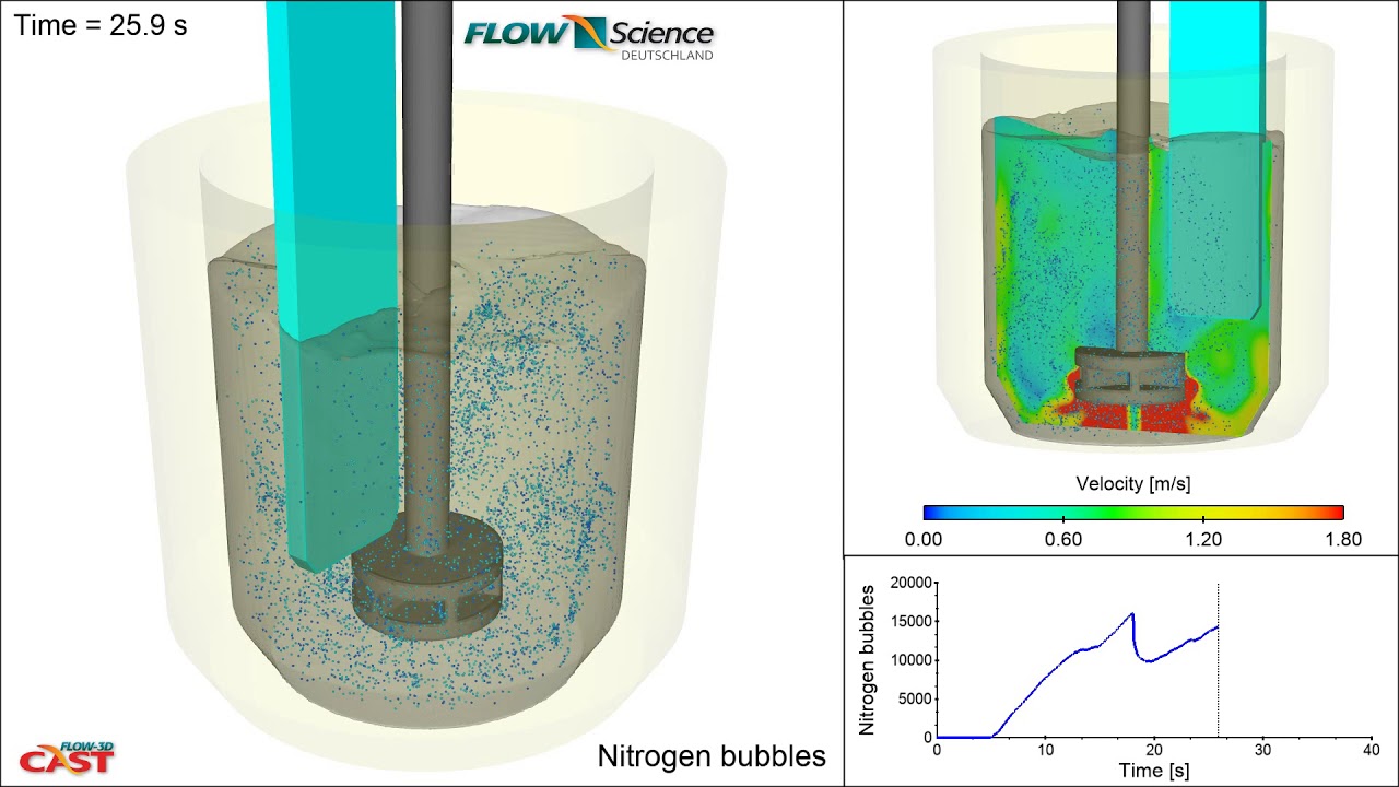
The mechanical properties of aluminum can be negatively affected by dissolved hydrogen in the metal. To mitigate this, a rotary degassing process introduces an inert purge gas (in this case, nitrogen) into the melt. The circulation created by the rotor allows the hydrogen to diffuse into the inert gas bubbles. FLOW-3D CAST allows the process engineer to model process parameters such as rotor design and speed to achieve optimal mixing and cast quality.
FLOW-3D CAST allows process engineers to accurately model the full high pressure die casting process, from ladle pour through solidification. This simulation shows the air entrained in the shot sleeve traveling into the mold. Key framing provides 360° views of the fill.
This is a simulation of an automotive flywheel or bell housing, showing velocity contours of an aluminum alloy during a fast shot of a high pressure die casting process. It is part of a design phase to evaluate different gating options. In this simulation, gates are angled at 45 degrees. The comparison between this and other gate angles helps visualize the effect of gates on this highly turbulent fill before addressing runner designs.
This simulation shows pouring a centrifugal casting of a horizontal pipe. The focus of this simulation is analysis of the filling pattern. The objective of the simulation was to prevent wall separation and have a smooth filling which did not trap air.
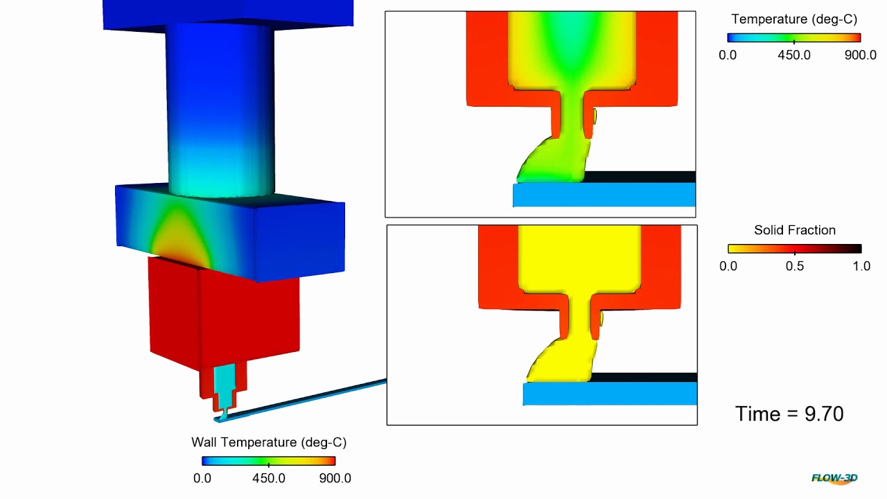
This simulation shows the production of door handles using the hot-chamber zinc die casting process. In zinc casting, there is a high technical requirement for the foundry to avoid production-related defects and discontinuities on the surfaces as best as possible. Simulations are a powerful tool for designers and foundrymen who want to achieve high casting quality. In FLOW-3D CAST the thermal die cycling process, mold filling and solidification can be accurately modeled, so that errors and problems during casting can be detected and avoided.
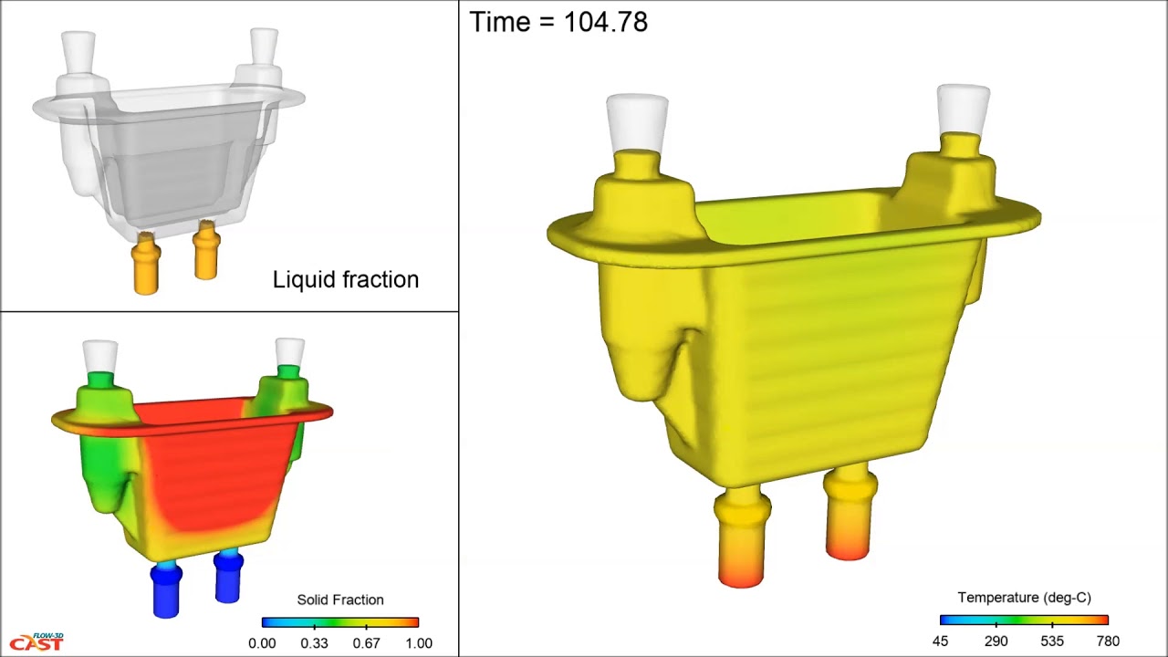
This simulation shows the filling of a planetary carrier with a ladle. The complete process from filling to solidification can be simulated with FLOW-3D CAST, including chills and exothermic risers, allowing for accurate prediction of casting defects and ensuring the best possible casting design.
This simulation illustrates the filling and solidification of ductile cast iron crankshafts, which was used to investigate a directional solidification into the risers. FLOW-3D CAST can be used to predict and avoid casting defects. Accounting for factors in cast iron including carbon expansion, primary (open) shrinkage cavities and secondary (internal) shrinkage cavities can be reliably displayed. Based on the size and position of the defects, the necessity of improvements to the casting design can be determined.
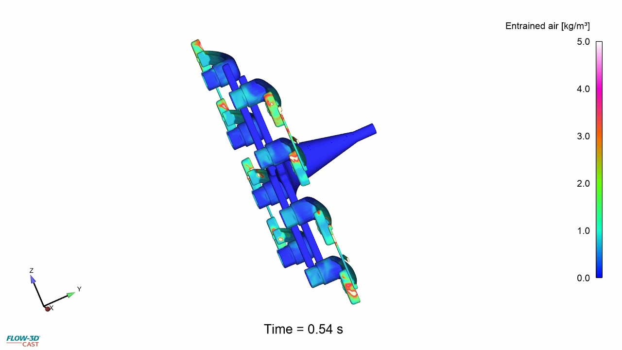
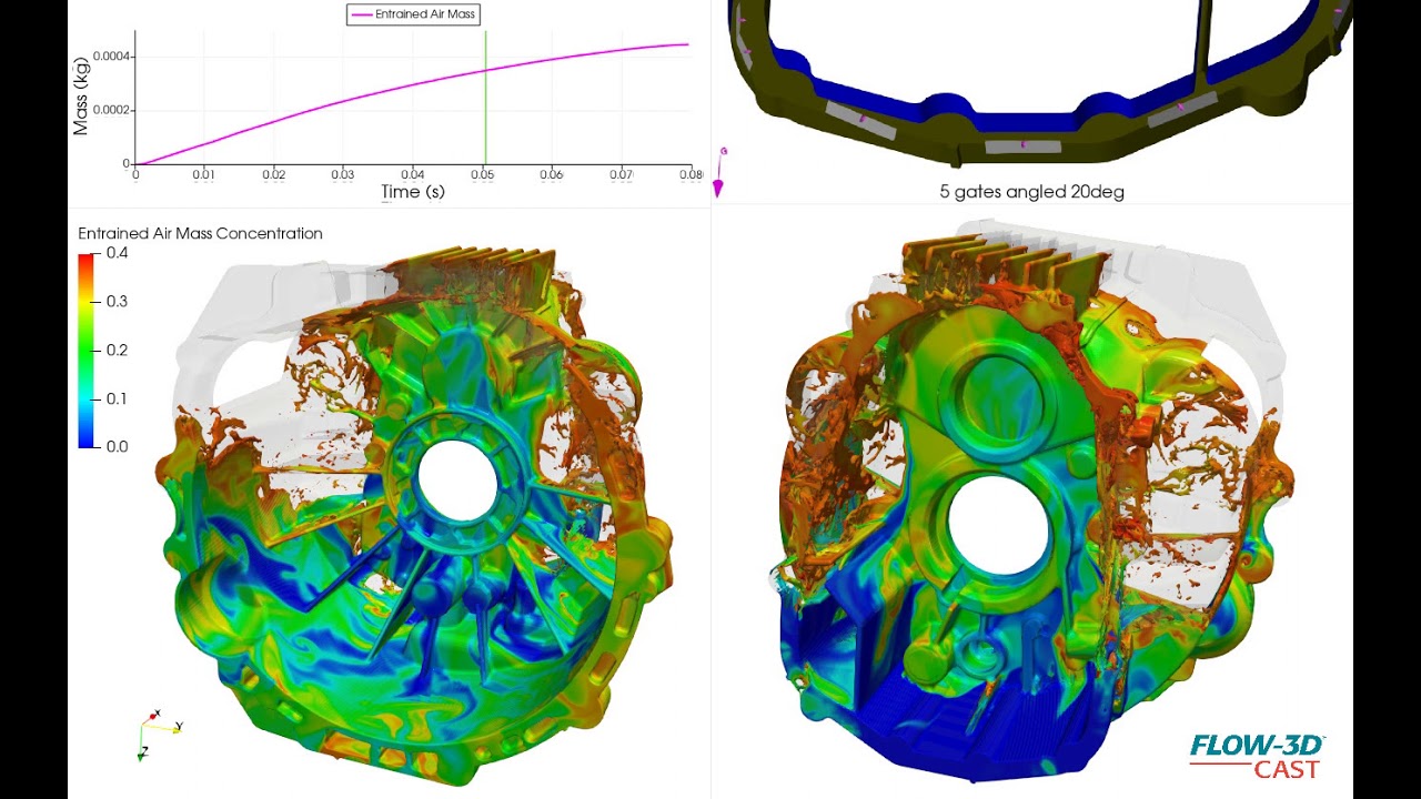
This is a simulation of an automotive flywheel or bell housing, showing air entrainment of an aluminum alloy during fast shot of high pressure die casting process. It is part of a design phase to evaluate different gating options. In this simulation, gates are angled 20 degrees, the contours indicate entrained air mass concentration.
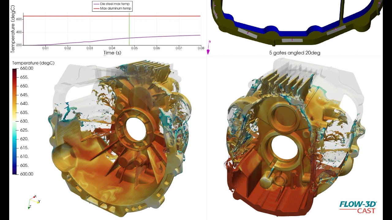
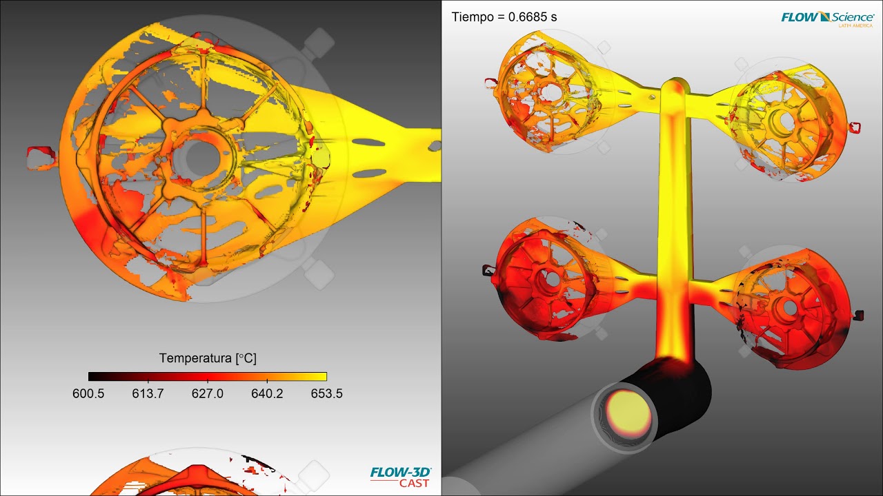
This is a simulation of an automotive flywheel or bell housing, showing thermal gradients during filling stage of a HPDC fast shot process.
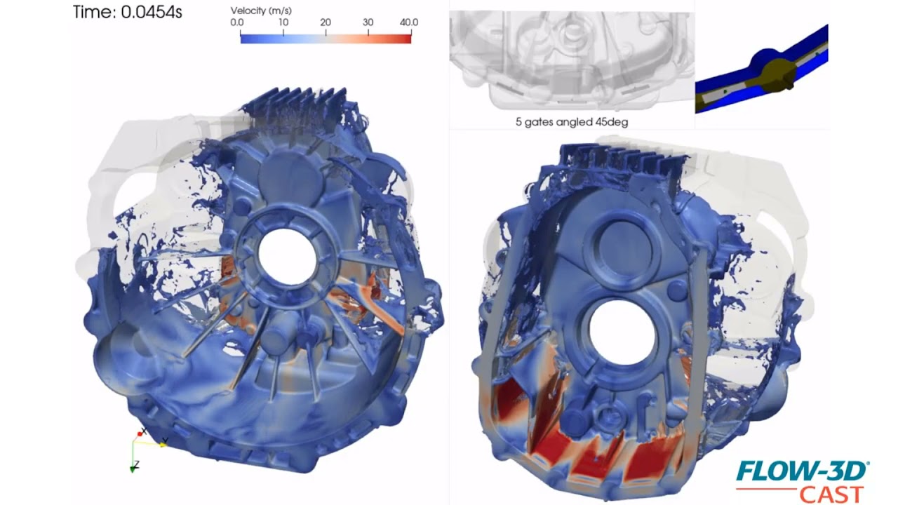
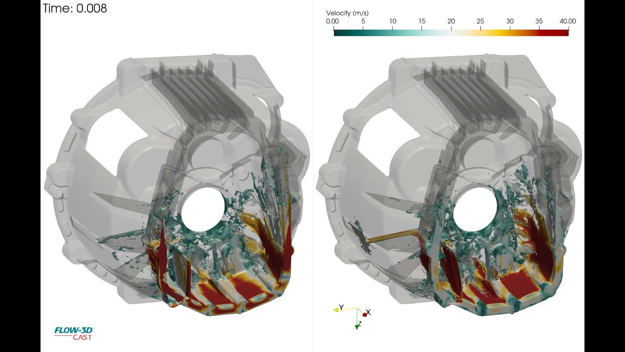
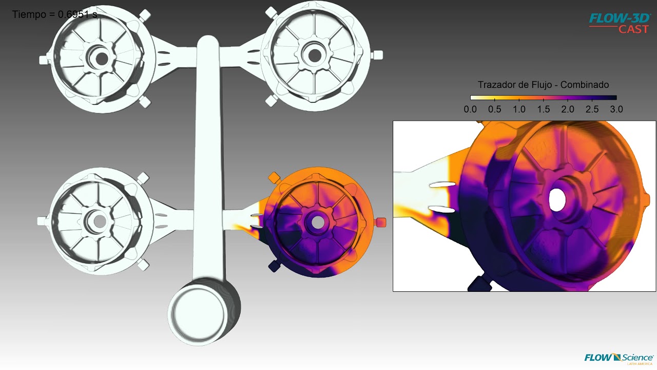
This is a simulation of an automotive flywheel or bell housing, showing velocity contours of an aluminum alloy during a fast shot of a high pressure die casting process. It is part of a design phase to evaluate different gating options. Shown here is a comparison of five gates, simulating filling from a runner below the parting line to accomplish an 80-millisecond casting fill. The left-hand simulation in the video shows gates pointed upward below the parting line, while the right-hand simulation shows gates at the same location, angled at 45 degrees.
This is a simulation of an automotive flywheel or bell housing, showing velocity contours of an aluminum alloy during a fast shot of a high pressure die casting process. It is part of a design phase to evaluate different gating options. In this simulation, gates point upward below the parting line. The comparison between this and other gate angles helps visualize the effect of gates on this highly turbulent fill before addressing runner designs.
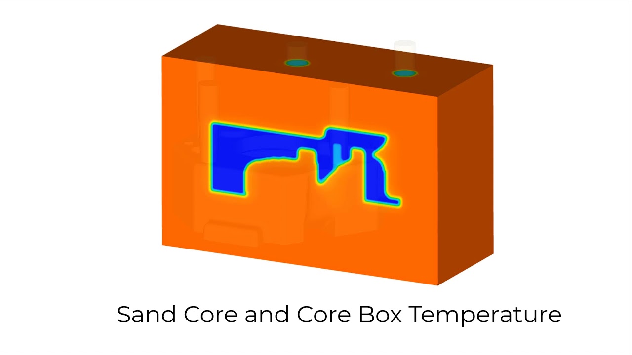
Sand cores shot in a hot box process are hardened using energy from the core box to cure the binder. This video shows the temperature distribution in the sand core as it is heated by the hot core box.
This video shows the filling pattern of H32 sand with a 2% binder additive being shot to produce an water jacket sand core. Notice that some of the regions are underfilled.
This FLOW-3D CAST simulation shows the evolution of amine gas through the porous, shot sand core, which is a water jacket for an internal combustion engine.
In this FLOW-3D CAST simulation, an intake manifold sand core shot with a sand/binder mixture containing 2% water by weight is dried by a hot (180 C) air purge. The blue region represents the water remaining in the sand core. The air vents are shown in gray. After 150 seconds of drying, the moisture continues to be pushed to the area where the most venting.
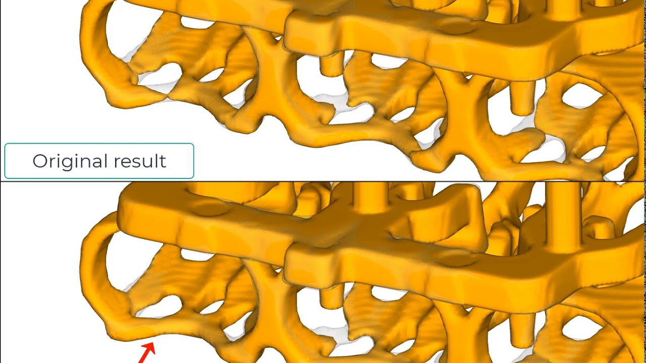
This FLOW-3D CAST simulation shows a comparison of the filling in the region where the air vent was added compared with the original result. The filling is now more complete in the region where the air vent was added. More vents can be easily added to address other underfilled regions.
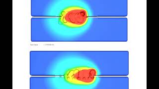
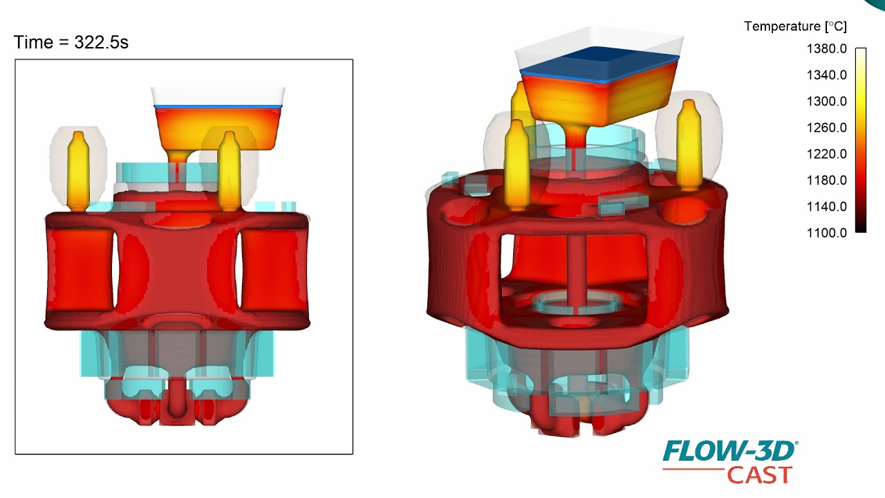
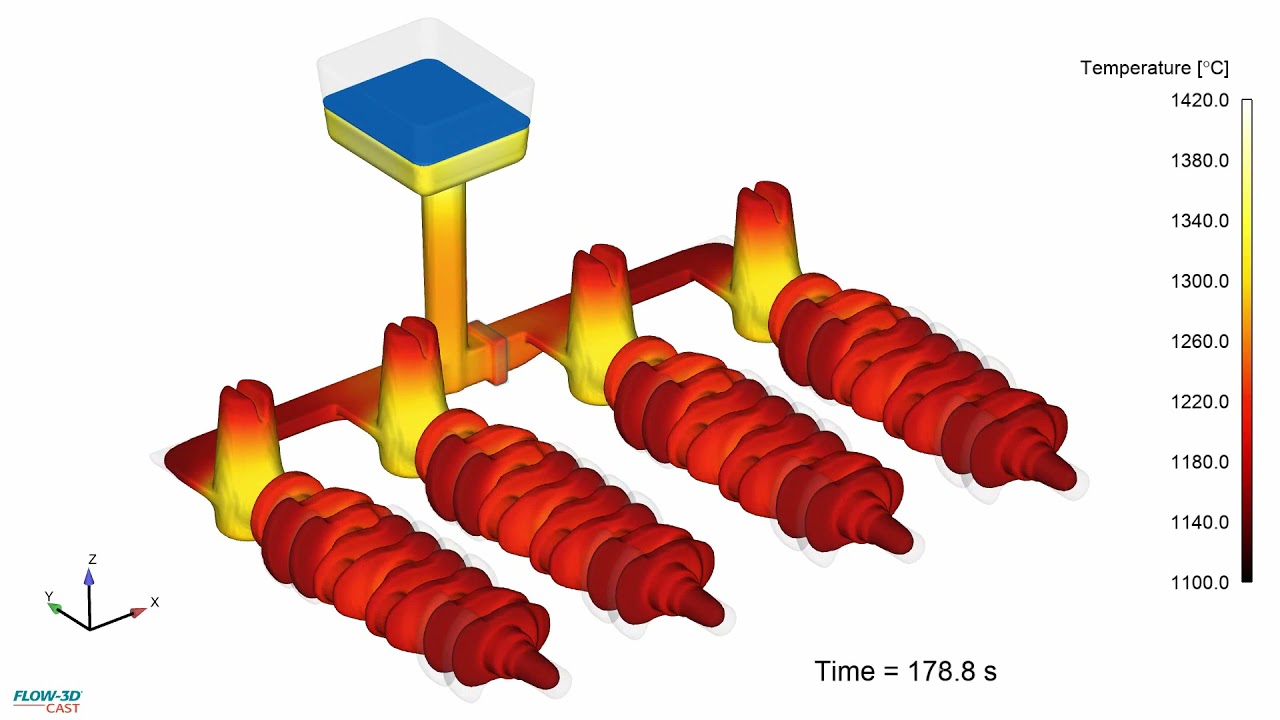
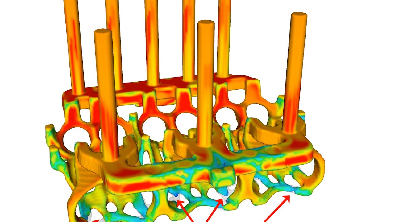
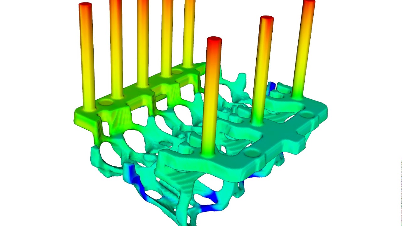
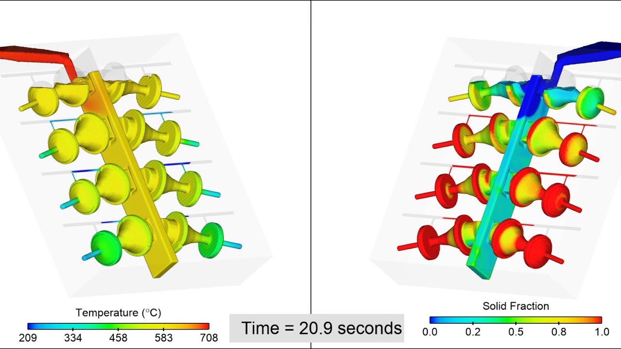
This simulation shows how the temperature distribution in the solidifying casting on the left and the solid fraction on the right. The feeders at the top of each part provide liquid metal to the casting as it solidifies and shrinks.
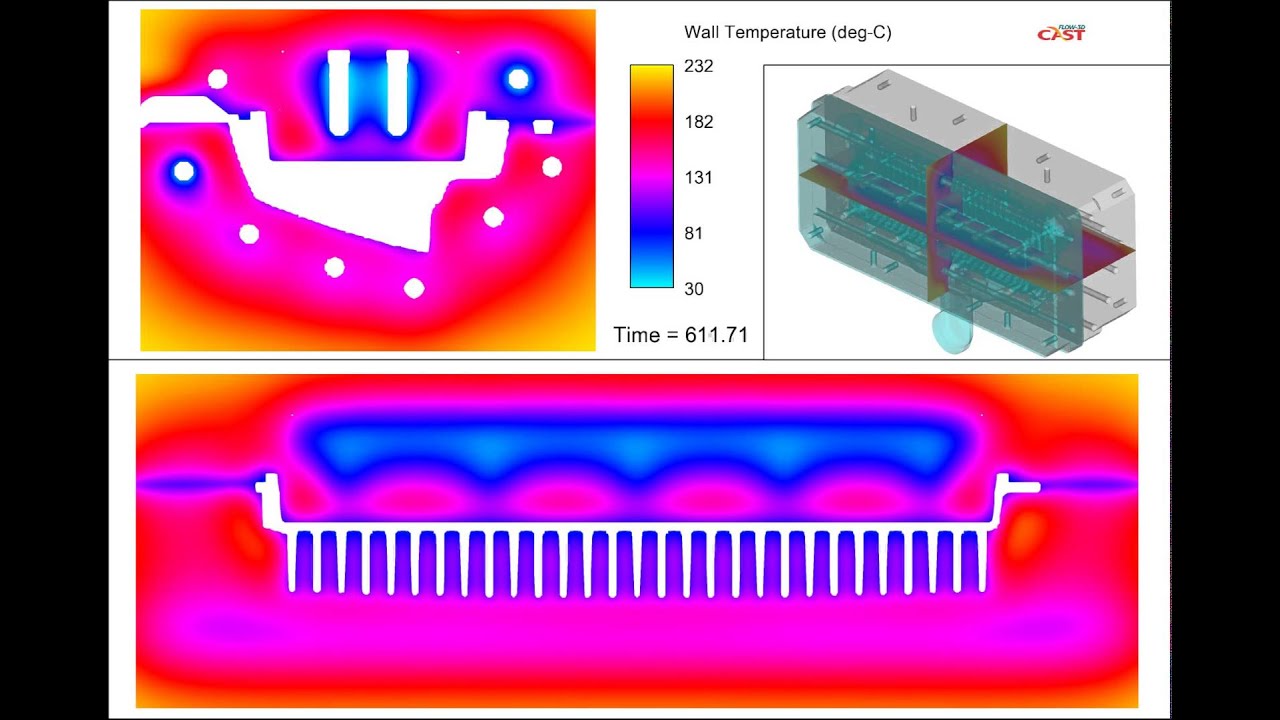
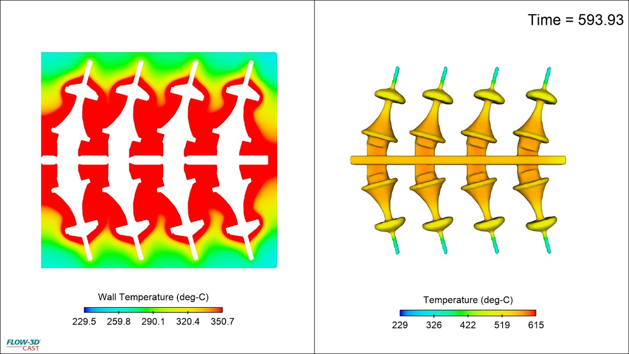
This FLOW-3D CAST simulation is a cross-sectional view of the die components during the entire tenth, and final, cycle. For this thermal die cycling analysis there were 6 stages in each cycle: 1. Solidification, 2. Ejection, 3. Open, 4. Blow Air, 5. Spray lubricant, 6. Closed, and we ran 10 total cycles. On the shop floor this would translate to 10 “shots” in order to develop this temperature profile. Notice the cooling profile at the parting lines, which are the horizontal contours, and how they change with time.
In this tilt pour casting of an aluminum ornamental fixture, the ladle is preheated to 500 C and is filled with Aluminum A356 at 708 C. The mold, made of H13 steel, is preheated to 200 C. The mold and ladle are rotated from horizontal to about 15 degrees from vertical allowing the melt to flow in a controlled fashion into the mold cavities. Air vents are placed on the mold cavities to allow air to escape. This simulation shows the temperature distribution in the melt and the solid fraction evolution as the mold cavities fill.
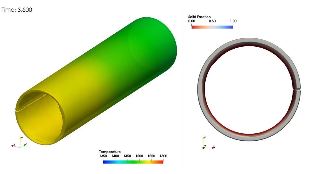
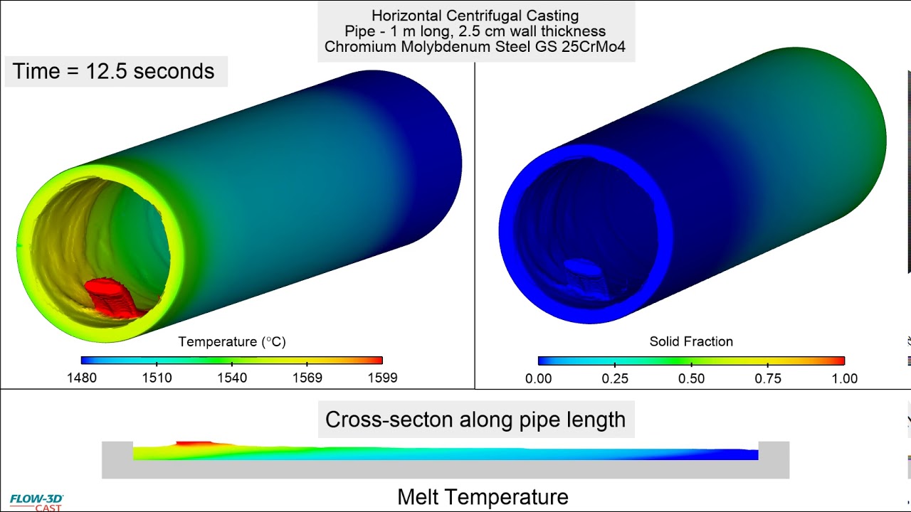
This simulation represents the filling stage of a pipe casting manufactured using a horizontal centrifugal casting process. The pipe is cast with Chromium Molybdenum Steel GS 25CrMo4 and is 1 m long and 2.5 cm wall thickness. The goal of casting pipes is to ensure that the thickness is uniform along its length. The cross-sectional view at the bottom of this video shows the distribution of the melt along its length. The melt should be uniformly distributed before solidification begins. Simulation can be used to study the impact of the initial temperature of the mold, the pour temperature, and the pour rate on the solidification during fill. Another important process parameter is effect of the mold rotation rate (500 rpm in this case) on the distribution of melt along the mold length. If the mold rotates too slowly, the melt will not pick up speed quickly enough to keep it attached to the mold surface resulting in raining which can cause production to stop for a significant period of time while the mold and the shop floor is cleaned.
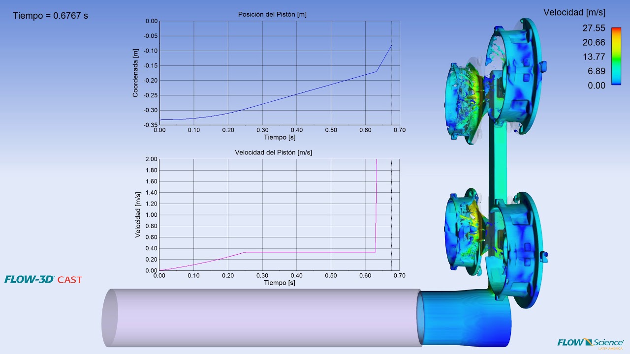
An important process parameter for controlling air entrainment in HPDC is the velocity profile of the shot plunger. Various plunger velocity profiles can be studied in FLOW-3D CAST to identify the amount of air entrainment for each. Additionally, a slow shot velocity profile calculator is included which helps to quickly estimate the best shot profile for minimizing air entrainment. Results analysis tools in FLOW-3D CAST provide a number of views of entrained air that make comparing the results of various shot profiles quick and easy. A global view of total entrained air is available as well as user-specified sampling volumes which allow local casting regions to be analyzed.
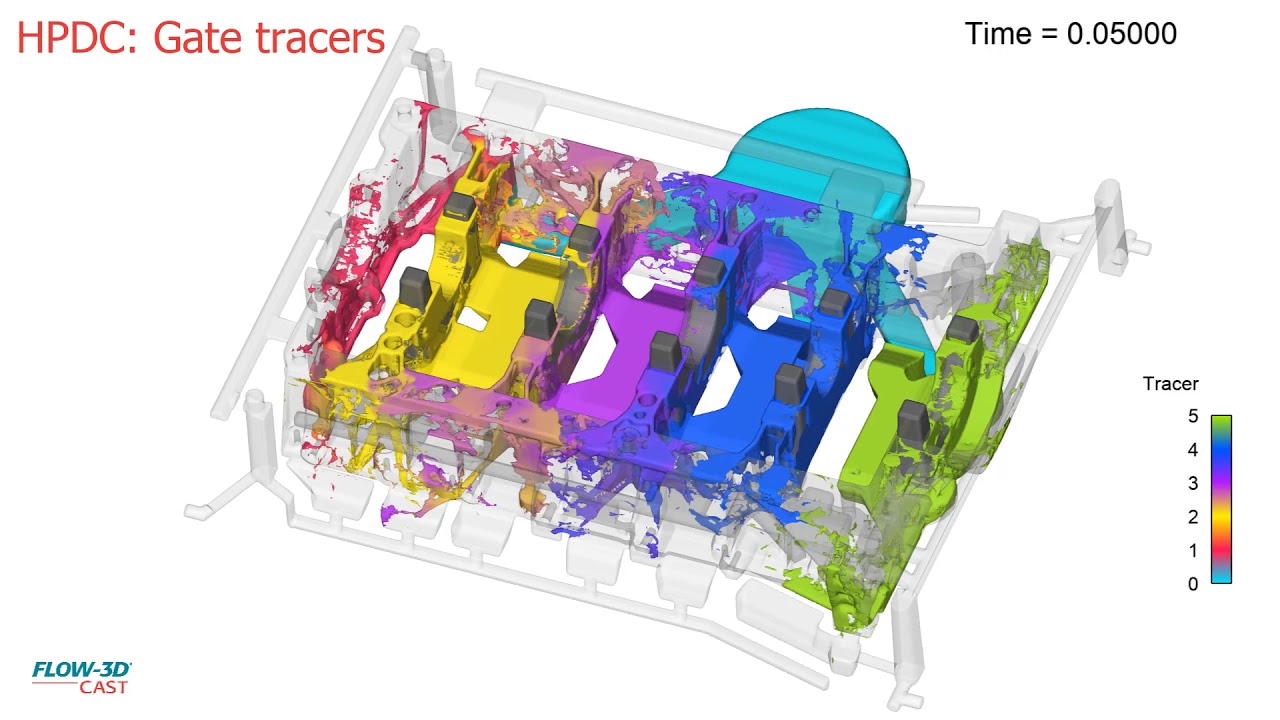
When designing the gating for an HPDC die, it is useful to understand the contribution of each gate to the overall filling pattern of the casting. Ideally, a well balanced filling with each gate filling the casting without significant cross flow will result in the best quality casting. FLOW-3D CAST provides gate tracers which color the melt based on which gate it entered the casting from.
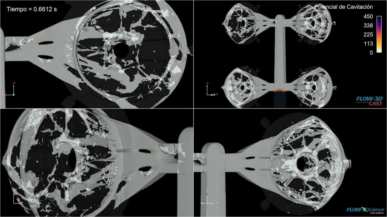
Because of the high velocities and accompanying low pressures created in HPDC processes, cavitation is possible. Cavitation bubbles collapsing on the die surface can create pitting which in turn causes surface quality issues on the casting as well as drastically shortening the life of expensive dies. The cavitation potential model in FLOW-3D CAST is a powerful tool for identifying areas on the die where cavitation is likely to occur. Rather than providing instantaneous indications of cavitation, which are not necessarily problematic, the cavitation potential model provides an overall estimation of the potential for cavitation damage by integrating the duration of the cavitation at each location on the die surface over the fill time.
Maintaining a melt temperature above the liquidus temperature is important in HPDC processes to prevent cold shuts and other defects. FLOW-3D CAST utilizes the most accurate filling simulations in the industry. With accurate filling simulations at their disposal, casting process engineers can identify pour temperature and die temperature profiles that minimize early solidification issues in designs.
FLOW-3D CAST provides users with many ways to instrument their casting simulations to provide a deep understanding of the behavior of their designs. This video shows the use of history probes placed in the gates to gain insight into the flow balance between gates. This information is very helpful, especially in multi-cavity castings where the flow between casting cavities varies.
This FLOW-3D CAST HPDC simulation of a rotor shows the filling profile with the addition of the shot sleeve dynamics.
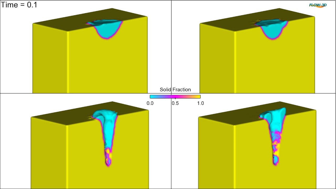
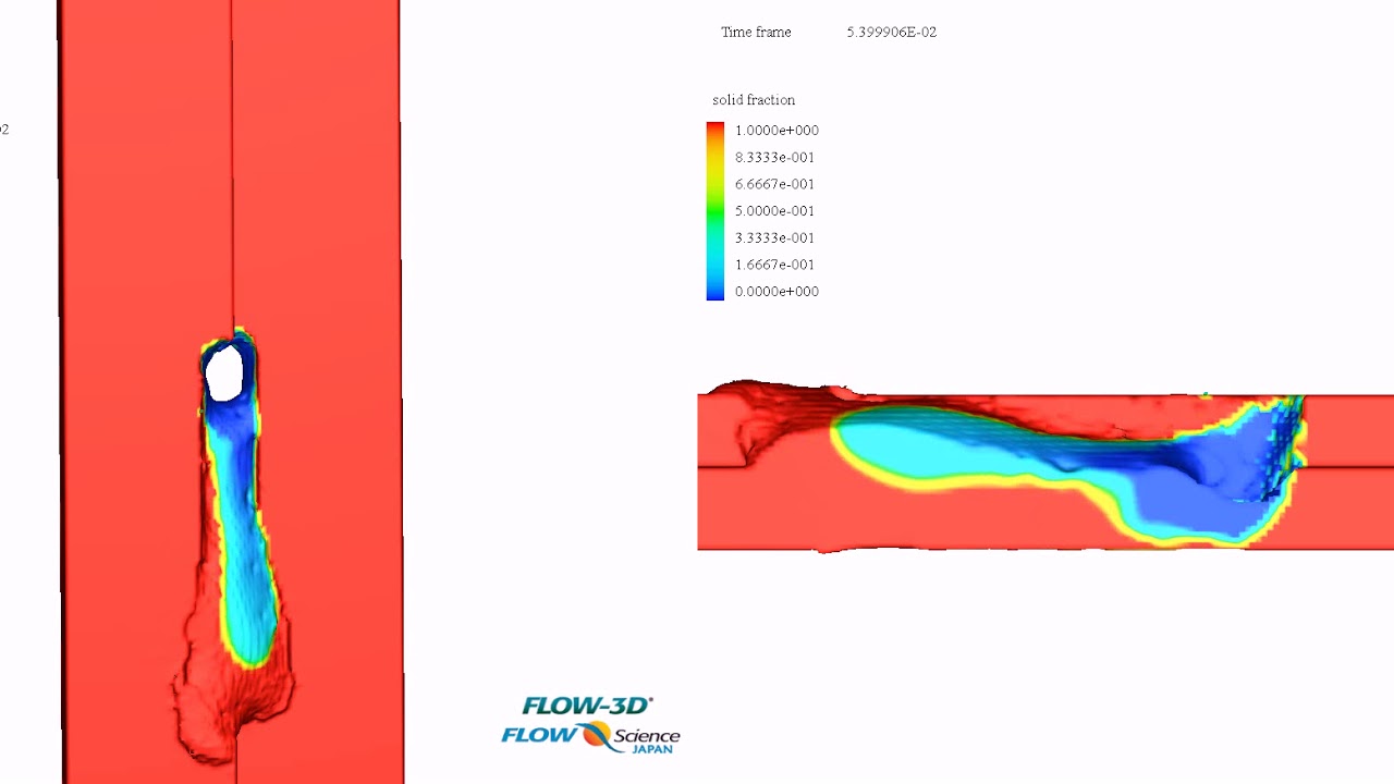
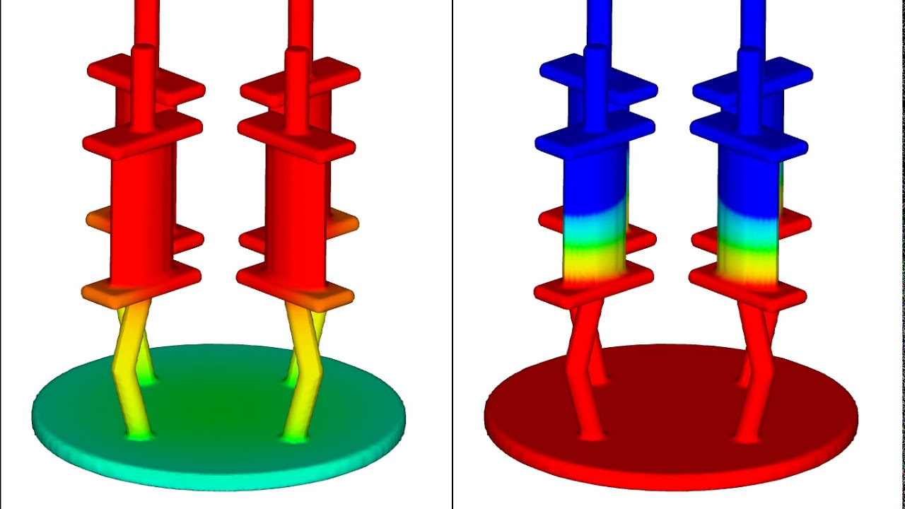
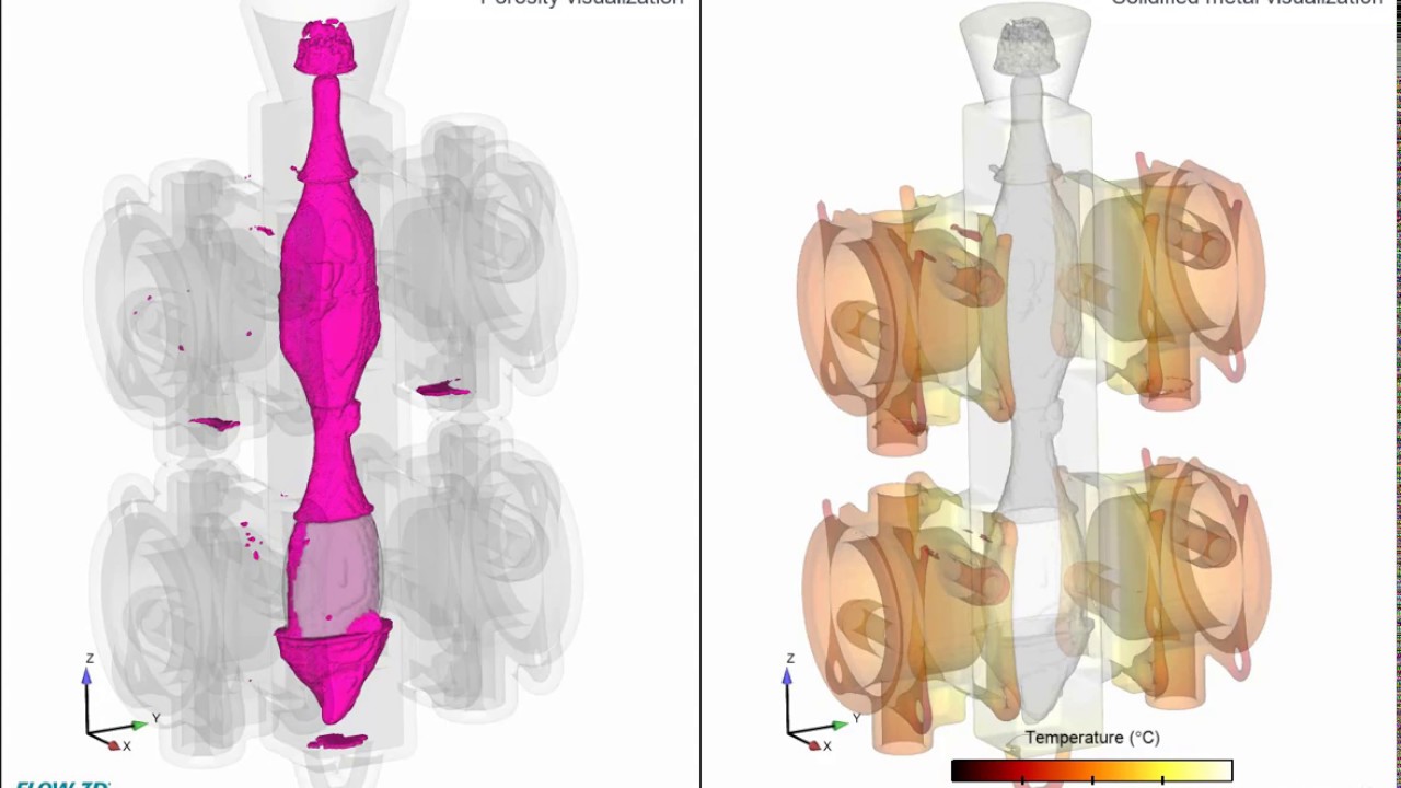
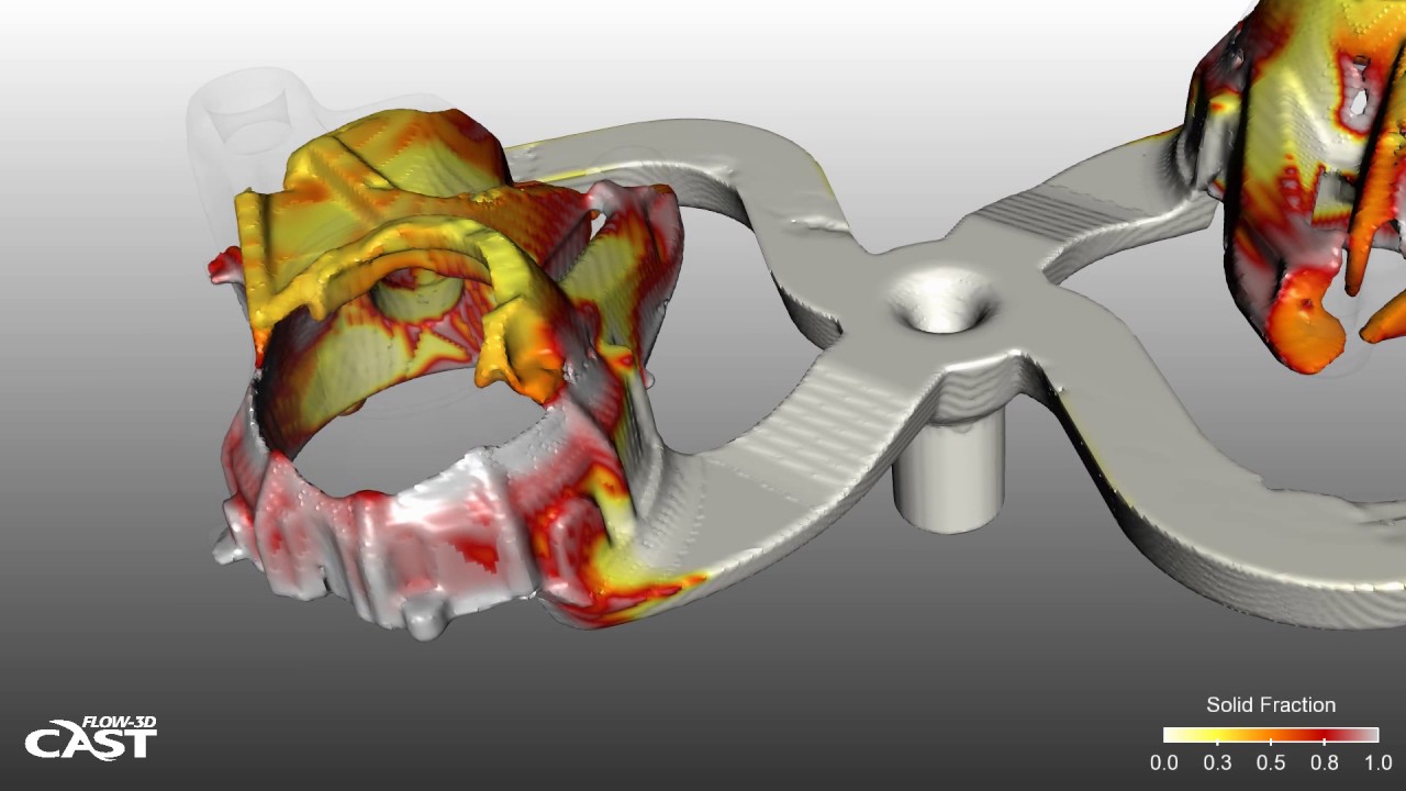
This FLOW-3D CAST simulation of a complex thin walled casting geometry shows the propagation of the solidification front.
This FLOW-3D CAST filling simulation of a complex thin walled part with salt cores shows the use of gate tracers to visualize rigging performance.
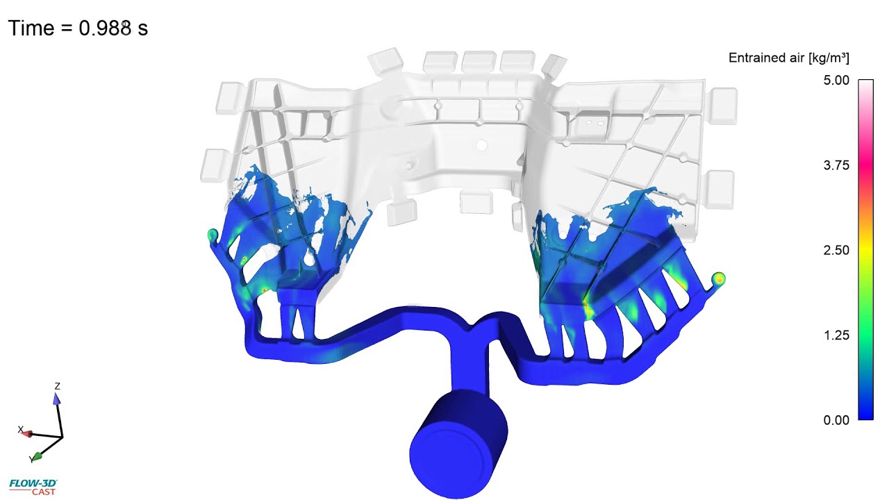
This FLOW-3D CAST filling simulation of a complex thin walled part shows the air entrainment variable to understand where defects can become an issue in the filling process. Visualization of air entrainment can be used to understand die venting, back-pressure, and areas of porosity.
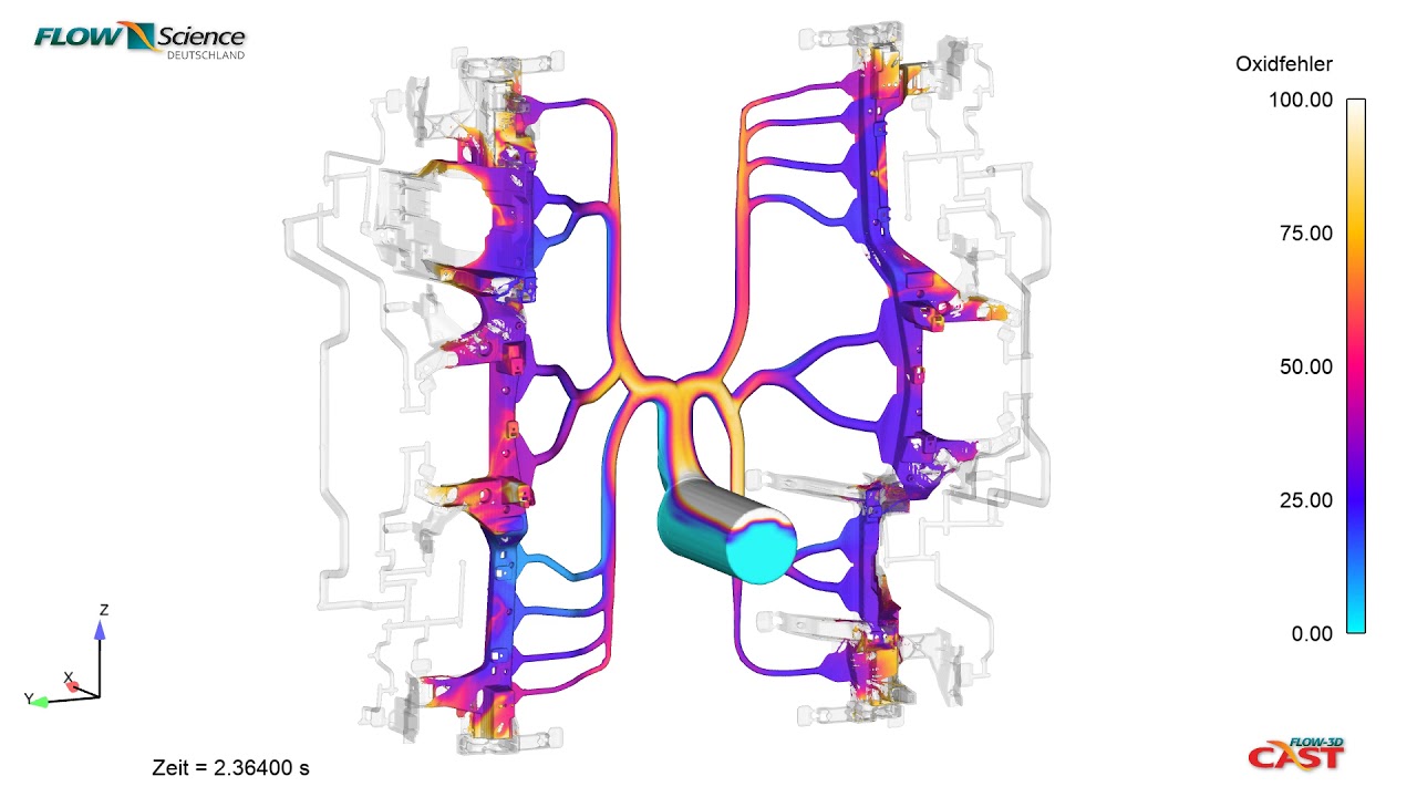
This FLOW-3D CAST filling simulation of an automotive component visualizes the oxide formation variable to understand where defects can become an issue in the filling process.
This FLOW-3D CAST filling simulation of a water pump shows the temperature distribution through a detailed filling pattern.
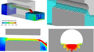
This simulation using FLOW-3D CAST‘s Centrifugal Casting Workspace represents the vertical centrifugal casting of an aluminum A356 flange. Melt is introduced into the mold via a vertical sprue at a rate of 5 kg/s. The mold is spun about its vertical axis at 500 rpm, providing an outward acceleration of 200 g at the surface of the mold. The left frame shows the pickup of the melt by the mold and helps determine the rate at which the melt distributes vertically over time. The upper right frame shows the solid fraction in the melt; this analysis helps determine the proper mold preheat to avoid premature solidification. In the lower right frame, the entrained air mass concentration is shown. As long as solidification does not occur prior to complete filling, all of the entrained air will be forced to the inner diameter of the casting, to be machined off later.
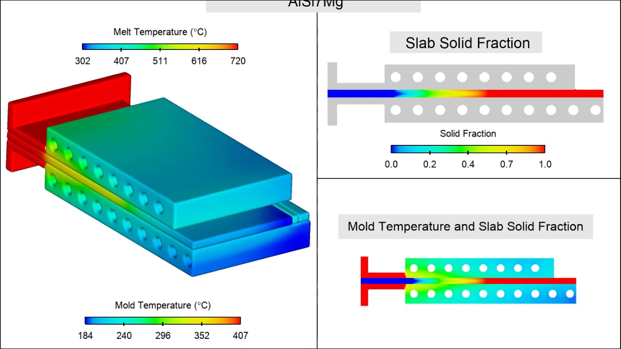
The goal of this simulation is to determine the cooling required to maintain a stable solidification profile during the continuous casting of Aluminum A356 plates. Melt is introduced into the process through a calcium silicate nozzle. Copper-Cobalt-Beryllium molds on both sides of the melt contain cooling channels to draw heat from the melt. The solidifying plate is drawn from the mold at a rate of 8 mm/sec.
The Investment Casting Process Workspace in FLOW-3D CAST v5.1 offers automatic shell generation in addition to advanced radiation modeling, in order to deliver extraordinary accuracy to aid the design modeling process.
This FLOW-3D CAST thermal die cycling simulation is used to assess the thermal saturation over multiple cycles.
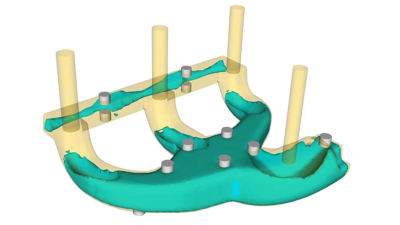
This FLOW-3D CAST filling simulation of a low pressure sand casting mold is used to assess defect propagation in the metal front.
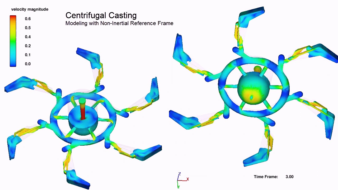
This centrifugal casting filling simulation with non-intertial reference frames allows the user to view the fluid front in the rotating mold. Simulation courtesy of Simulated Engineering.
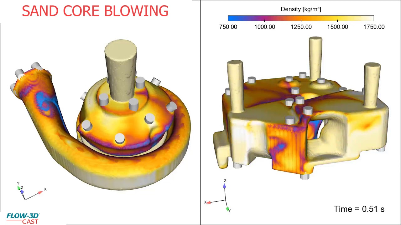
This FLOW-3D CAST sand core blowing simulation of a turbo charger housing is used to assess the density of the sand mixture during shooting.
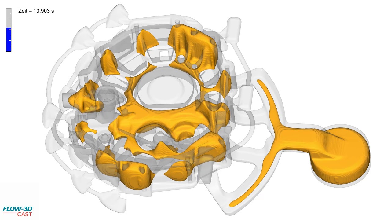
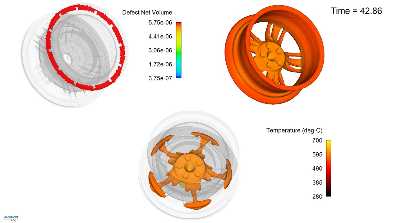
This FLOW-3D CAST simulation of an aluminum wheel low pressure die casting visualizes the solidification front and predicted net defect volume based on porosity. This example is part of a webinar on FLOW-3D CAST’s Low Pressure Die Casting Workspace.
This FLOW-3D CAST simulation shows the filling analysis done to identify an area where a cold shut is produced. Simulation courtesy of XC Engineering. This example is part of an on-demand webinar on FLOW-3D CAST’s Low Pressure Die Casting Workspace.
