
FLOW-3D Playlist
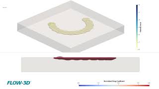


The new droplet/bubble source model allows either spherical droplets or bubbles to be emitted at defined intervals from a point source. This source can be either stationary or its motion can be defined in a tabular fashion. The initial velocity of the droplet or bubble can also be defined in three dimensions. All physical models are compatible with this model so that typical applications such as porous media flow, evaporation/solidification, and surface tension can be simulated. In this example, a droplet source moves in a circular pattern while ejecting droplets downward at a velocity of 10 m/s into a porous medium to create a ring-shaped design.
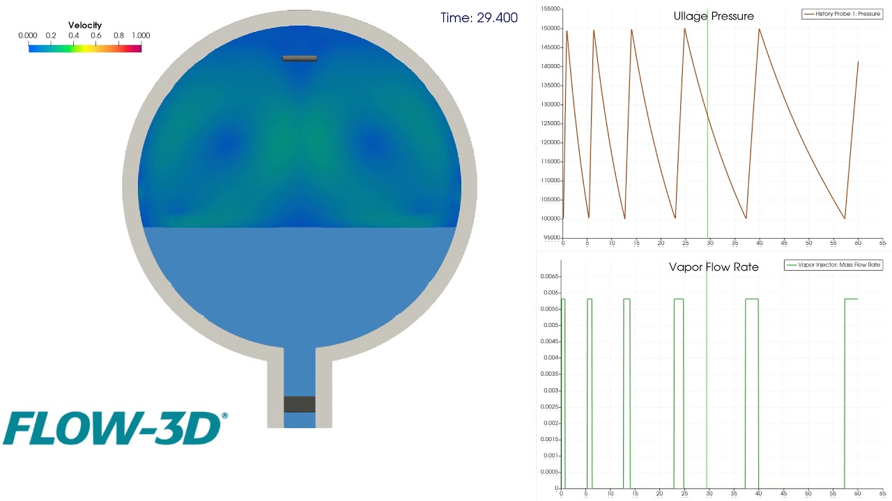
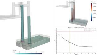
In this example, a pump (dark grey rectangle) in a cryogenic tank feed pipe pulls liquid oxygen from a propellant tank at a constant flow rate. As the liquid oxygen drains, a mass/momentum source (grey bar at top) is triggered by Active Simulation Control when the pressure in the ullage drops below a specified value. Pressurization is turned off when the ullage pressure rises above a specified value.
Viscosity is defined as a function of both solid content (density) and strain rate. In this example a dense fluid region slides down into a quiescent pool which at time zero is layered with a dense settled fluid region and clear water above.
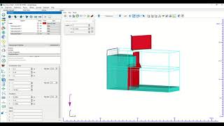
FLOW-3D‘s interactive geometry creation and editing is better than ever, and now includes new interactive tool selection including rotate, move and resize; enter rotate, move, or resize mode by clicking the action and selecting the geometry to modify; and clicking the up arrow icon or hitting the ESC key will return the user to a normal select mode.
FLOW-3D’s new axial pump model allows users to mimic the net effect of an axial pump in their simulations. There are two options with respect to the pump behavior. The first option is to prescribe either a volumetric flow rate or a flow velocity through the pump so that the fluid is moved at the specified rate. This option is appropriate when an operating flow rate is provided for the pump. The second option provides a more complete definition of the pump operation based on a pump performance curve.
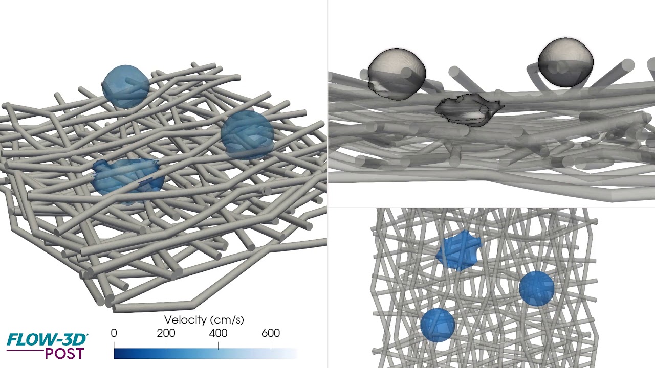
Here, FLOW-3D is used to simulate drop impingement on a fibrous bed, looking at the propagation of the fluid front as it relates to surface tension, contact angle, and viscosity.
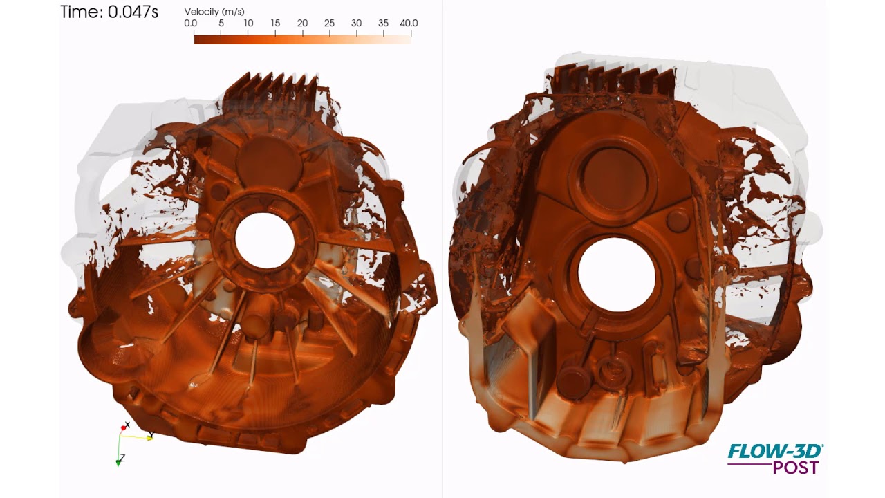
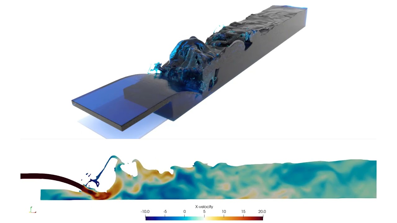
This is a simulation of an automotive flywheel or bell housing, showing velocity contours of aluminum alloy during fast shot of a high pressure die casting process. This is part of a design phase to evaluate different gating options, the 5 gates here simulate filling from a runner upward and below the parting line to accomplish 80-millisecond casting fill. The animation helps visualize the highly turbulent fill clearly indicating first and last regions to fill. Among other things, it helps in understanding the moving metal front and potential cold shots that result from this gating configuration.
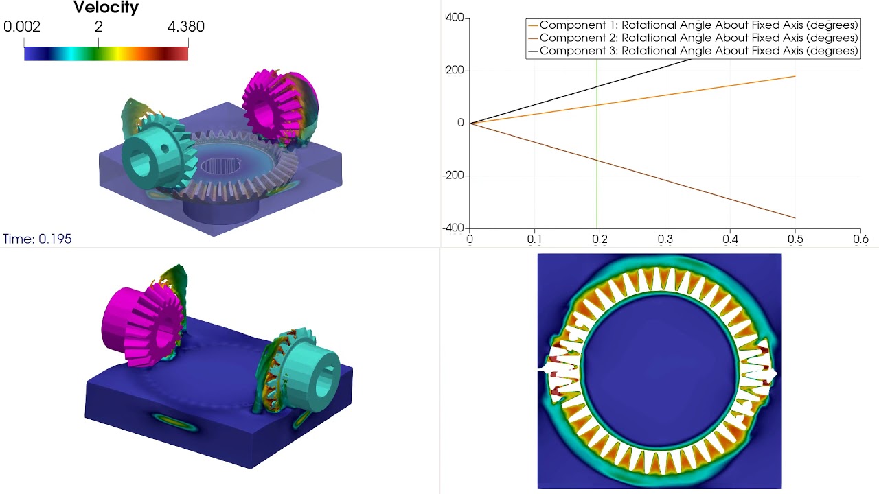
This simulation depicts gear-gear and gear-oil interactions in a gear box as an example of fluid-structure interaction. The left gear possesses prescribed rotation. The two gears undergo a series of collisions with each other on their teeth causing rotation of the right gear. The right gears rotation is also affected by its interaction with the motion of the oil.
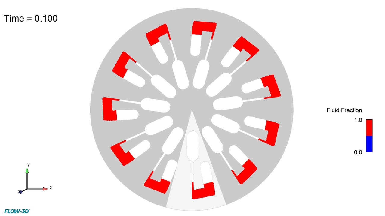
This FLOW-3D simulation shows the kinetic energy fluctuations for a microfluidic compact disc rotating at 7000 rpm. At this rotation speed, compared to the 1000 rpm speed (https://youtu.be/stAYg1nAr2E), steady state is reached faster but with rapidly fluctuating water levels. Read the blog.
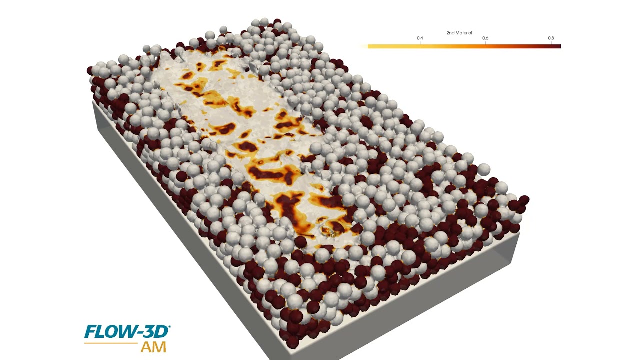
Micro and meso scale simulations using FLOW-3D AM help us understand the mixing of different materials in the melt pool and the formation of potential defects such as lack of fusion and porosity. In this simulation, the stainless steel and aluminum powders have independently-defined temperature dependent material properties that FLOW-3D AM tracks to accurately capture the melt pool dynamics.
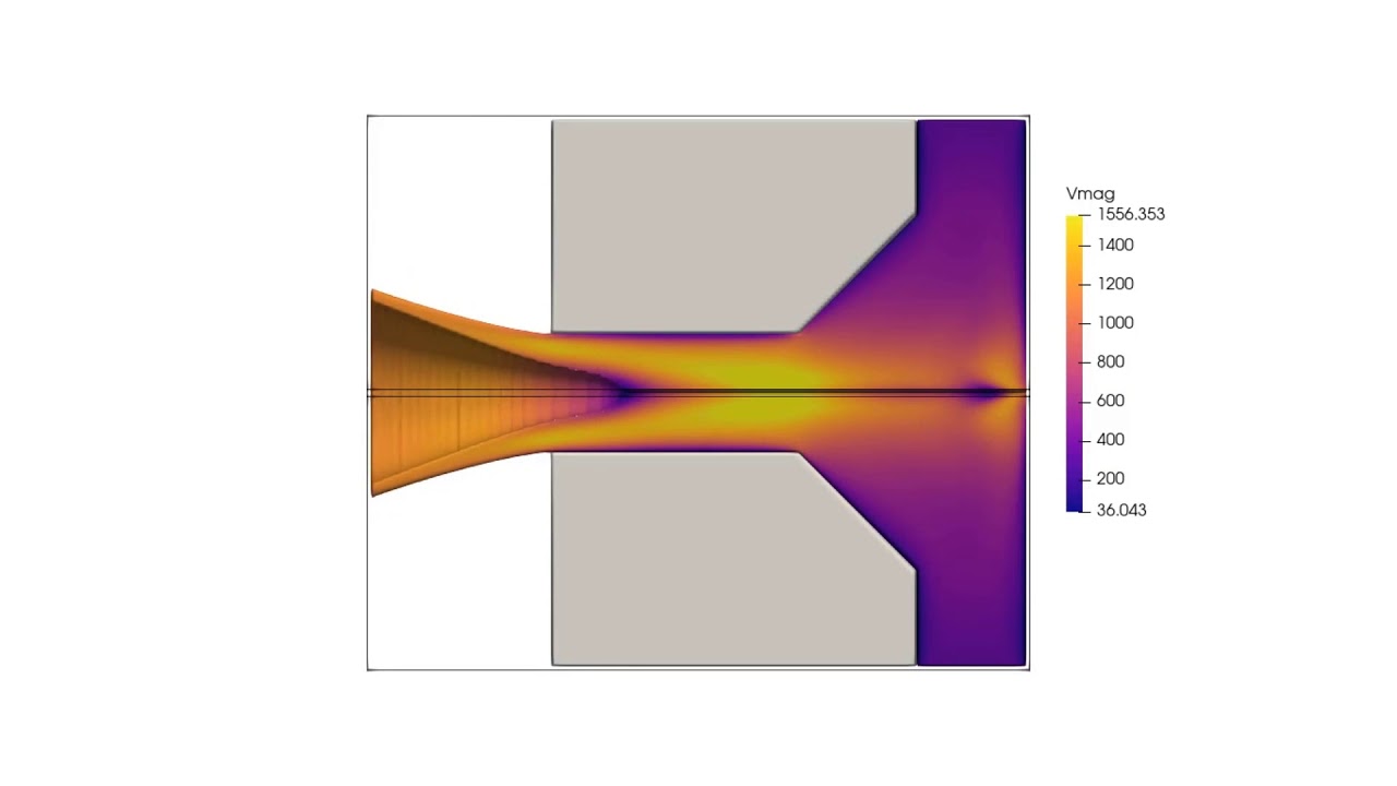
In this CFD simulation of a swirl spray nozzle, postprocessed with FLOW-3D POST, fluid spins at a high velocity before the nozzle. When fluid exits the nozzle, the centrifugal force sends the fluid away from the axis, creating a vortex core inside the nozzle.
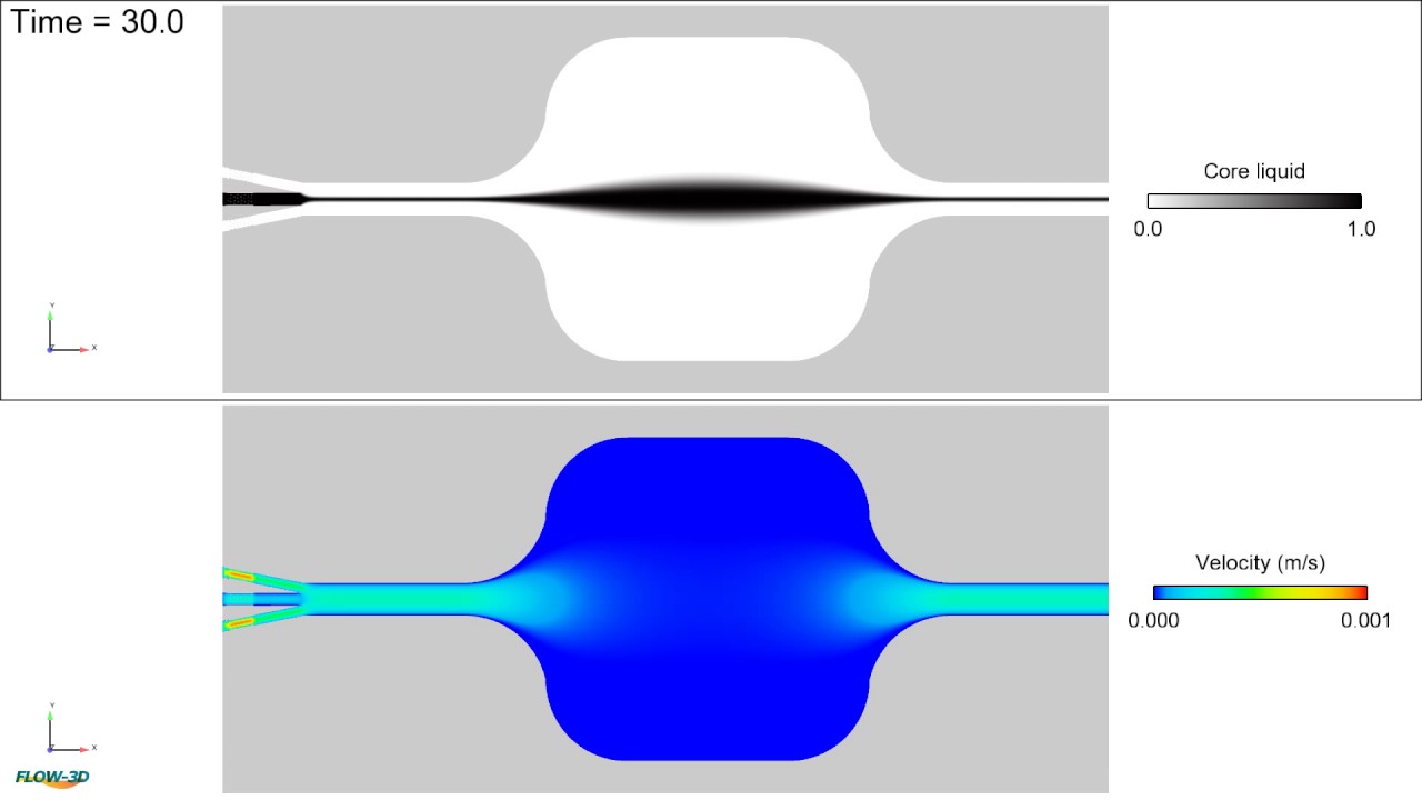
Animation showing the formation of biconvex shape lens using a core flow (black fluid) rate of 3 mL/h and cladding flow (white) rates of 7 mL/h.
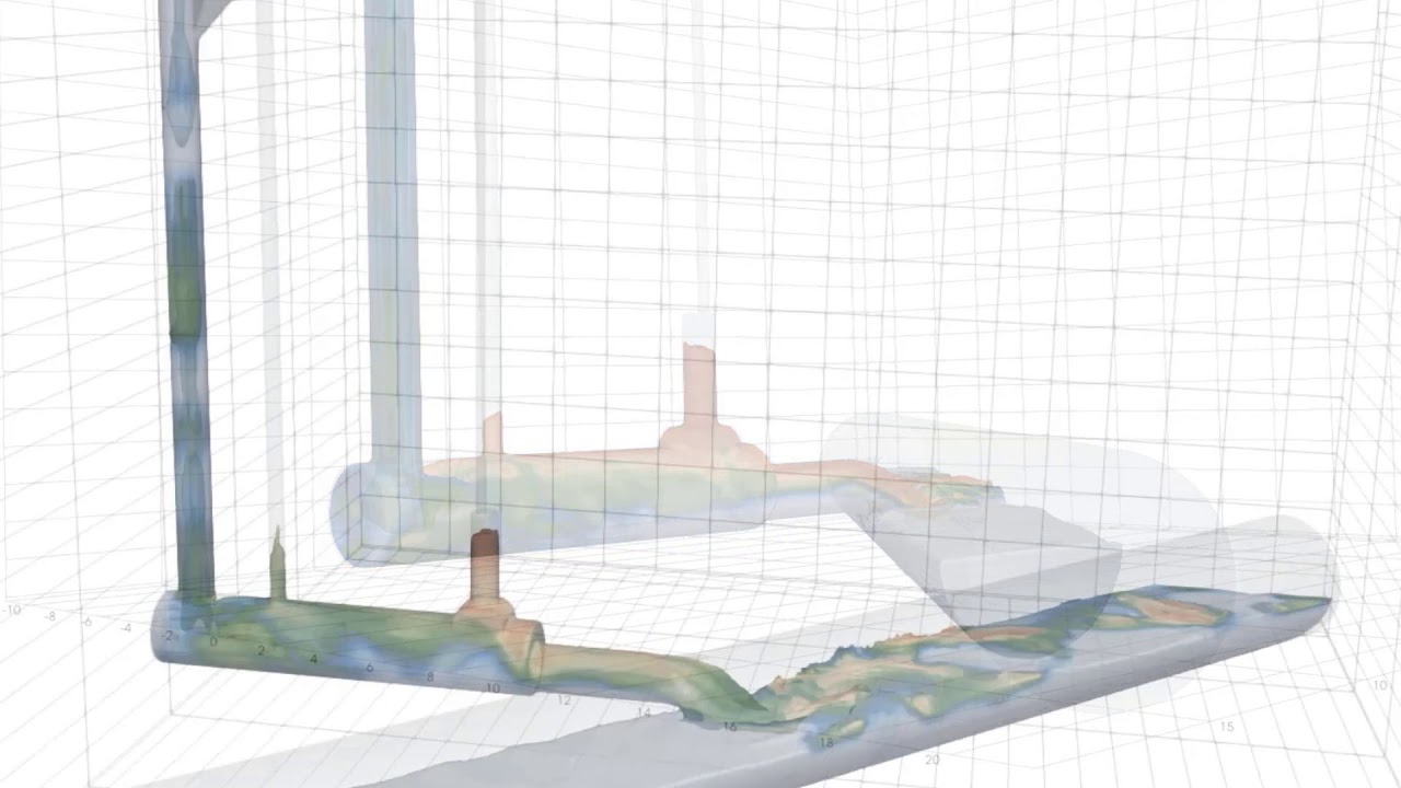
Under certain flow conditions tangential dropshaft are effective by promoting the formation of a vortex core in the dropshaft as the flow is propagated to lower elevations. FLOW-3D HYDRO offers multiple modeling approaches to help engineers model free surface flow characteristics, and evaluate the energy dissipation, downdraft and air entrainment behaviors of the system.
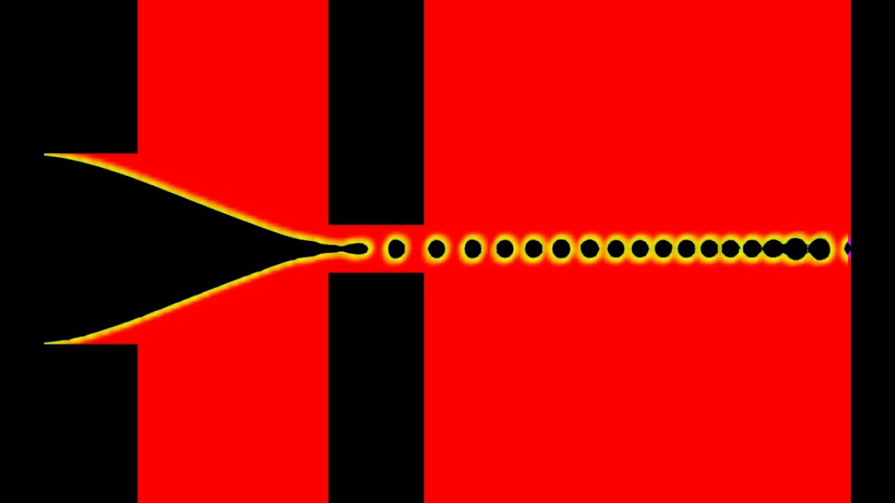
Flow focusing is a microfluidics technique to generate droplets or bubbles using hydrodynamics. In this video, FLOW-3D is used to simulate the flow focusing process.
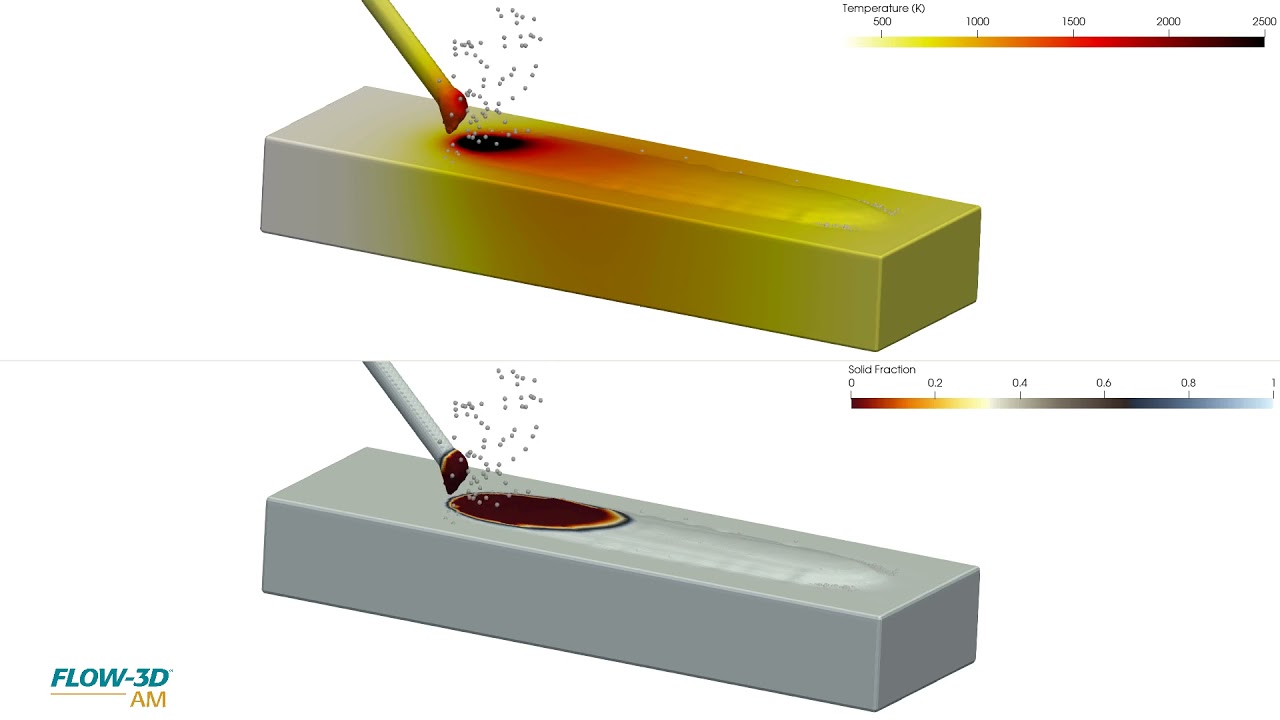
In this FLOW-3D AM simulation of a powder-based directed energy deposition process, powder particles are melted onto a substrate by way of a laser. Tracks are laid next to and on top of eachother where they solidify to build a 3D part. This simulation can be used to study the influence of process parameters like laser power, powder injection rates, scan speeds and material properties on fusion and subsequent mechanical properties.
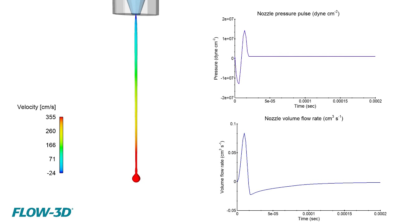
This simulation is looking at droplet ejection of a piezo driven inkjet. These drop-on-demand (DoD) printheads are used for a variety of applications from conventional printing processes to additive manufacturing processes such as binder jetting and material deposition. FLOW-3D allows for analysis of how system parameters and fluid rheology affect droplet velocities, uniformity, and overall consistency in the printed image or part.
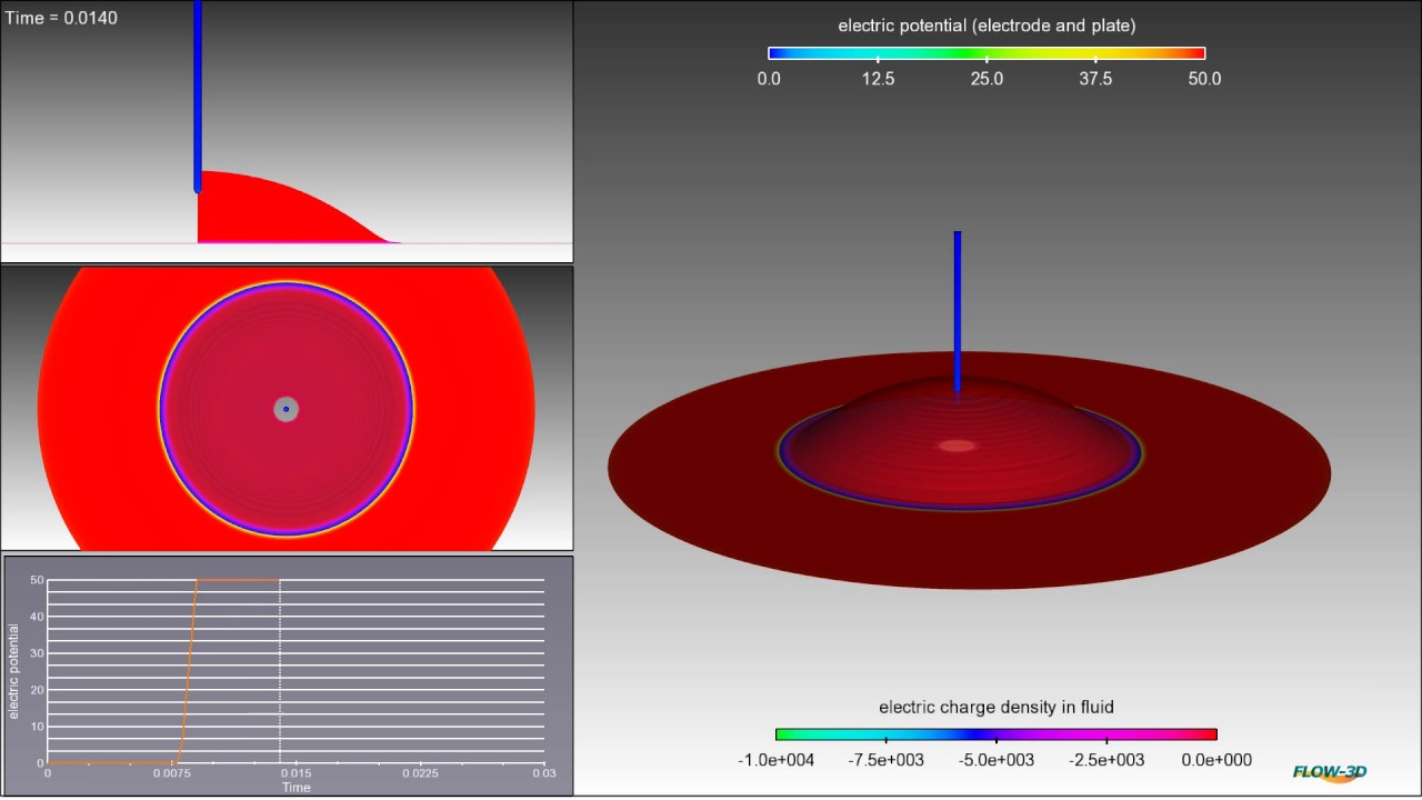
Electrowetting is a technique used to change the apparent contact angle of a dielectric fluid under the influence of electric potential. In this example, the fluid is originally hydrophobic and beads on the surface. However, when a 50V potential difference is applied, the fluid is forced to wet the surface becoming hydrophilic.
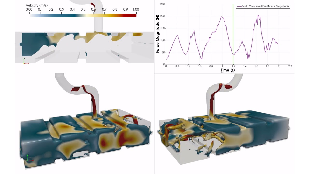
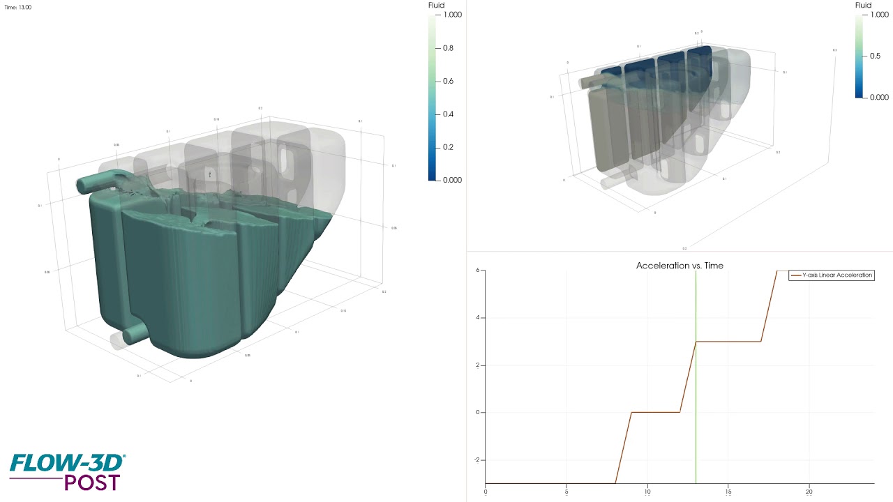
Automotive fuel tanks hold significant fuel mass and are subject to constant vehicle accelerations and decelerations. This presents a structural issue for tank material due to the impact forces. Additionally, sloshing of fuel can cause incorrect reading or damage to measurement devices. Shown here is a simulation in FLOW-3D of fuel sloshing under acceleration plotting velocity contours. The graph shows transient force magnitude on fuel tank.
In this FLOW-3D AM simulation of a wire/powder-based directed energy deposition process, powder particles and wire feed are melted onto a substrate by way of a laser. Tracks are laid next to and on top of each other where they solidify to build a 3D part. This simulation can be used to study the influence of process parameters like laser power, powder injection rates, wires feed rates, scan speeds and material properties on fusion and subsequent mechanical properties.
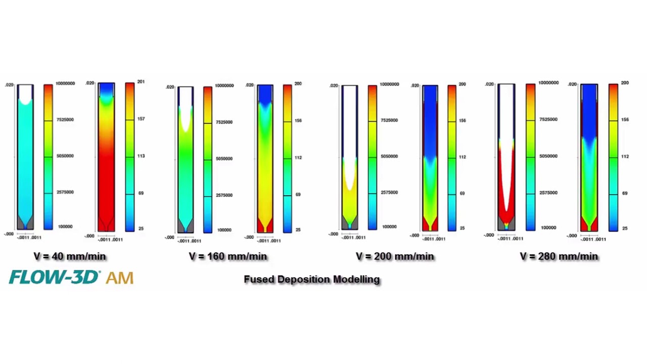
Fused Deposition Modeling (FDM) is one of the most widely used 3D printing techniques, but not much research has been done on polymer extrusion and flow characterization. How do extrusion speeds and nozzle geometries affect the FDM process? This is a question that researchers from Technical University of Denmark tried to answer using CFD models built in FLOW-3D AM. This simulation video shows the polymer flow within the liquifier at different extrusion speeds. At speeds greater than 160 mm/min, oscillations set in and the process becomes unstable. A recirculation zone forms near the interface of the solid filament and the melt zone, which prevents the polymer melt from flowing upstream.
Rendering of a FLOW-3D HYDRO dense jet simulation, this visualization uses volume thresholds in FLOW-3D POST, Flow Science’s new postprocessor available across all FLOW-3D products.
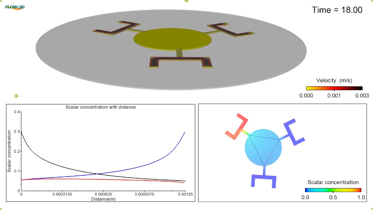
This FLOW-3D simulation of a 2-D microfluidic palette demonstrates a spatio-temporal control on the generated gradients. The source and sink are rotated at an angular velocity. Also, after every t seconds, the active access port is deactivated and the next port is turned on. To see the live status of the diffusion inside the chamber, three line probes are placed in the simulation (marked in red, blue and black, respectively, in the bottom right window of the simulation). Read the blog.
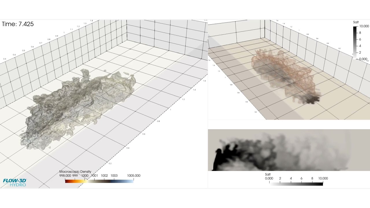
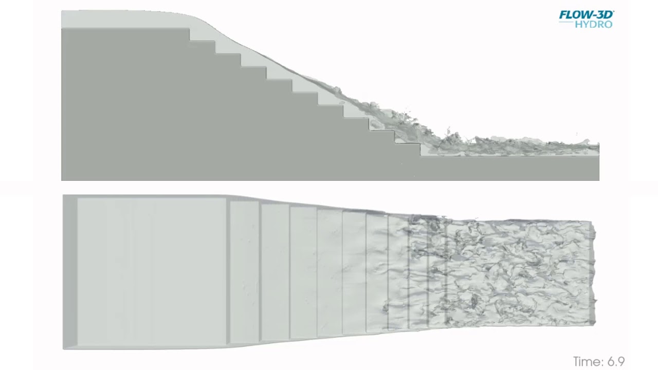
Turbulence generated from the solid surface of a staircase spillway can eventually propagate all the way to reach the free surface, at which point the flow may become highly aerated from that inception onwards. FLOW-3D offers multiple approaches that allow engineers to characterize the onset of aeration and estimate subsequent bulking of the flow.
This simulation is looking at a L-PBF process in which the laser transverses the substrate in zigzag pattern. The remelting that occurs between tracks can influence the microstructure of the solidified metal, so it is important to understand how to optimize hatch spacing and scan strategy to achieve desired temperature gradients and cooling rates.
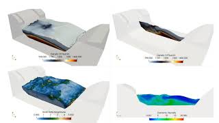
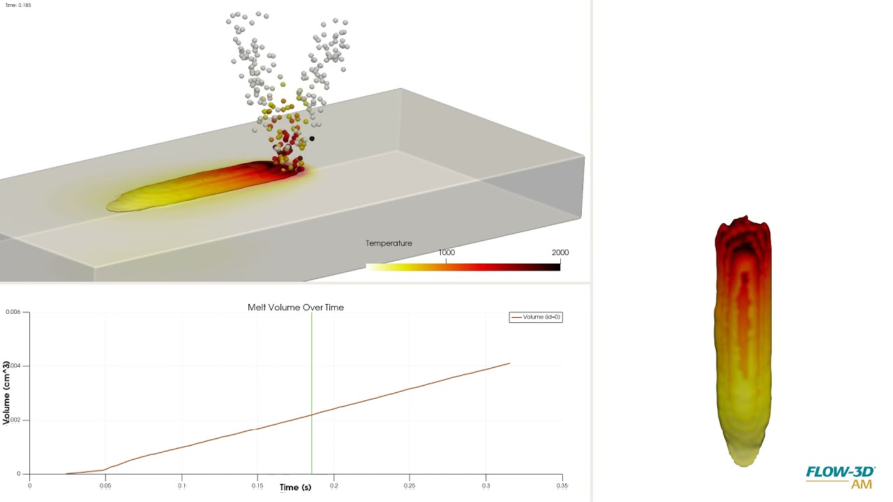
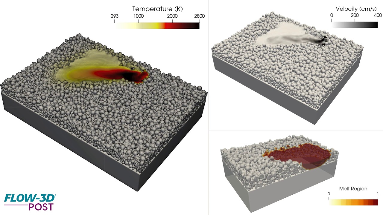
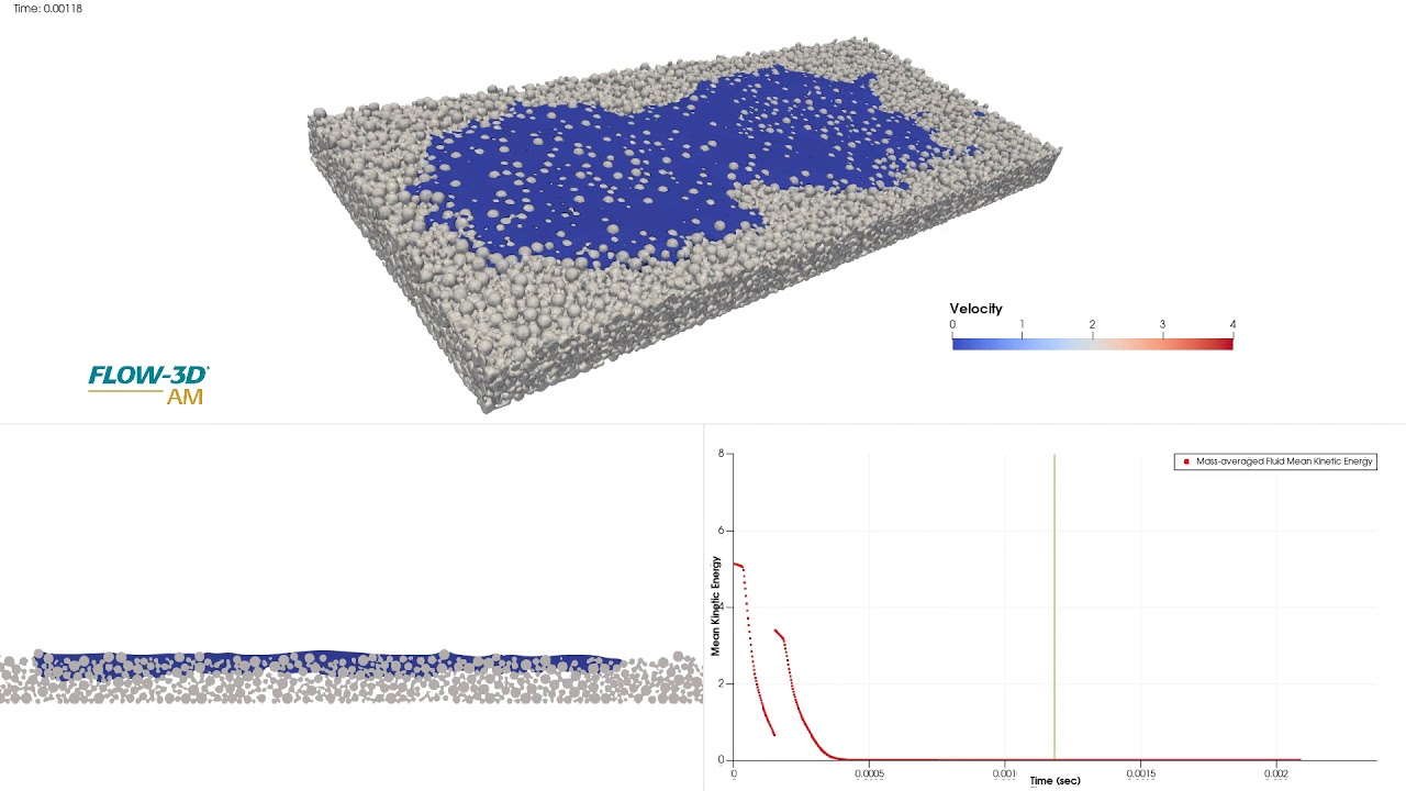
In this simulation, we look at fluid impact on a powder bed. The material properties of the fluid and the process parameters such as powder size distribution and droplet velocities influence the spreading, coalescence and penetration of the fluid into the powder bed. Capillary forces help the fluid to penetrate further into the powder bed. The mass-averaged kinetic energy plot shows that the fluid eventually reaches steady state indicating the depth of penetration and seepage into the medium. Learn more about modeling capillary action through CFD at www.flow3d.com.
FLOW-3D POST ray trace rendering of a FLOW-3D HYDRO model of an energy dissipating baffled outlet. Learn more about FLOW-3D HYDRO‘s advanced CFD modeling solution for the civil and environmental engineering industry at www.flow3d.com/hydro
Degas bottles have been extensively used in engine coolant systems in automobiles, mainly to de-aerate the coolant fluid and provide room for expansion. This FLOW-3D simulation of a Degas bottle uses the full 2-fluid model to simulate both the coolant and air phases, which are represented with fluid fractions of 1 and 0 respectively. The video shows how the coolant in the system behaves under different vehicle accelerations.
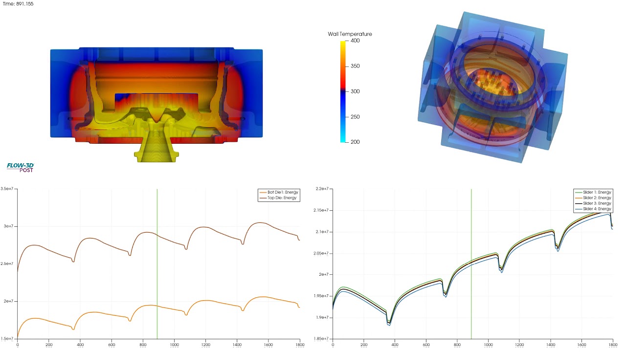
Thermal die cycling is used to heat the mold components to proper operating temperatures before starting production. Proper analysis of die thermal management protocols can inform extended die life and part quality. Simulation can be used to assess areas of heat saturation over many cycles. Additionally, once a thermal steady state has been determined, the profile can then be used to inform a filling simulation with greater accuracy.
Development of a hydraulic jump simulated with FLOW-3D HYDRO. The top view is a ray-traced rendering of the flow; the bottom view, a 2D slice of the velocity field. This simulation was postprocessed with FLOW-3D POST, our new postprocessor for visualization and analysis across FLOW-3D products. Learn more at www.flow3d.com/hydro
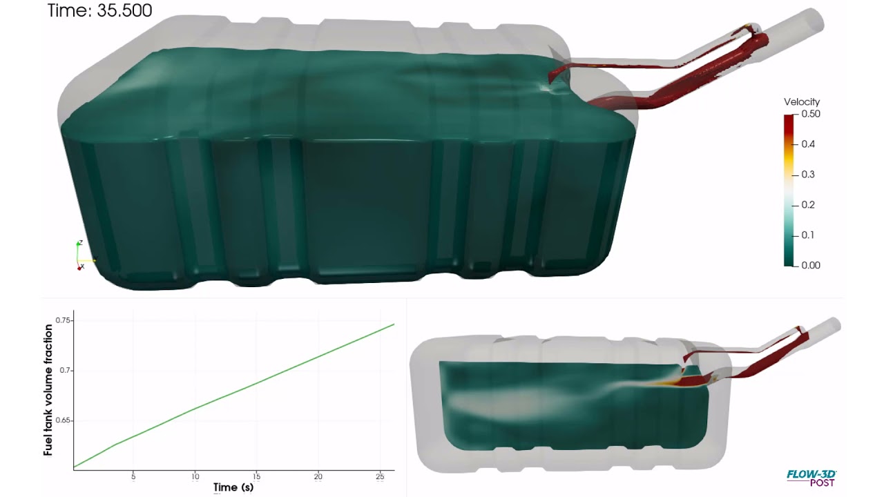
Automotive fuel tanks are designed to account for compressibility of fuel vapor while refueling and to prevent early shut-offs at fuel stations. This can cause shuddering of fuel vending units, eventually causing damage. Improper shut-offs can also cause fuel spillage or fire. Typically, fuel tank shapes are designed based on chassis or frame limitations. Shown here is a simulation of a simple fuel tank through refueling where a secondary vent tube (smaller tube on top) is simulated to allow fuel to completely fill the tank and initiate timely shutoff. This can be done either as a single and multi-fluid analysis in FLOW-3D, simulating vapor backpressure and fuel flow. The animation shows velocity contours of fuel and volume fraction of the fuel tank being filled.
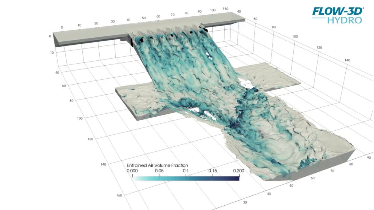
With the increased availability of high performance computing platforms, large scale simulation of complex free surface flows can now include very high meshing density, which delivers for the user a very high accuracy representation of the flow. This labyrinth weir model includes the free surface flow, as well as an estimate of air entrainment.
This simulation uses FLOW-3D HYDRO‘s Moving Objects model, which couples solids with the surrounding fluid. The full mass tensor of the ship is needed to accurately characterize the hull dynamic behavior. In this side launch, the ship is released from a standby position to slide down rails before impacting the the water.
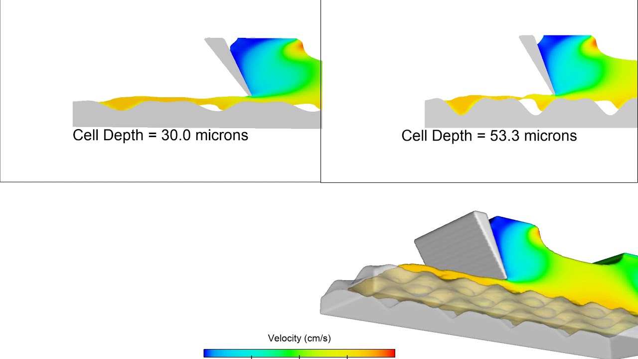
This FLOW-3D simulation of a gravure coating looks at the effect of cell depth on deposition. The model compares two cell depths: 30 microns and 53.3 microns. The 30-micron cell depth allows for a much more uniform deposition, which will transfer to the resultant coating.
In this simulation, FLOW-3D captures a cascade defect in a forward roll coating process. Due to increased roll speed of the web roller on the top, the dynamic contact line becomes unstable which allows for air to be entrained into the coating fluid.
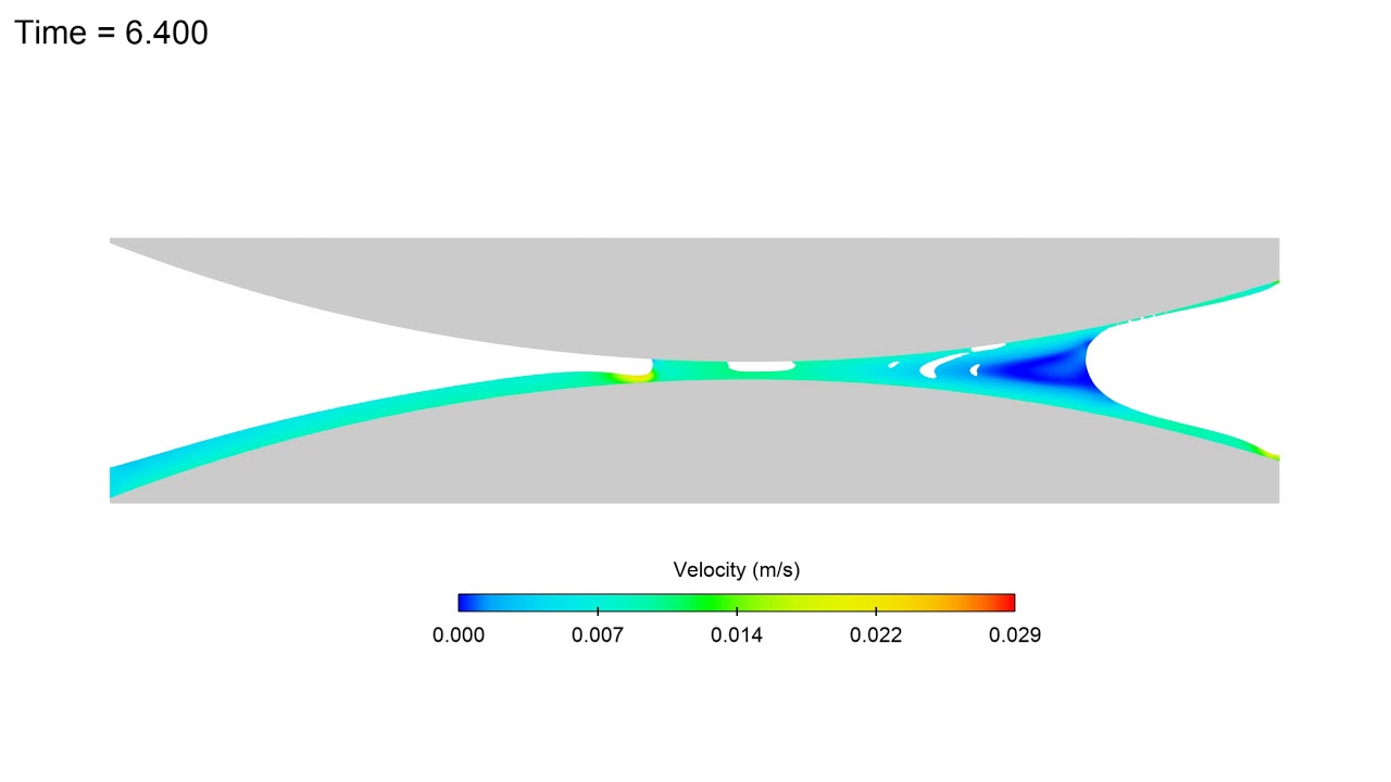
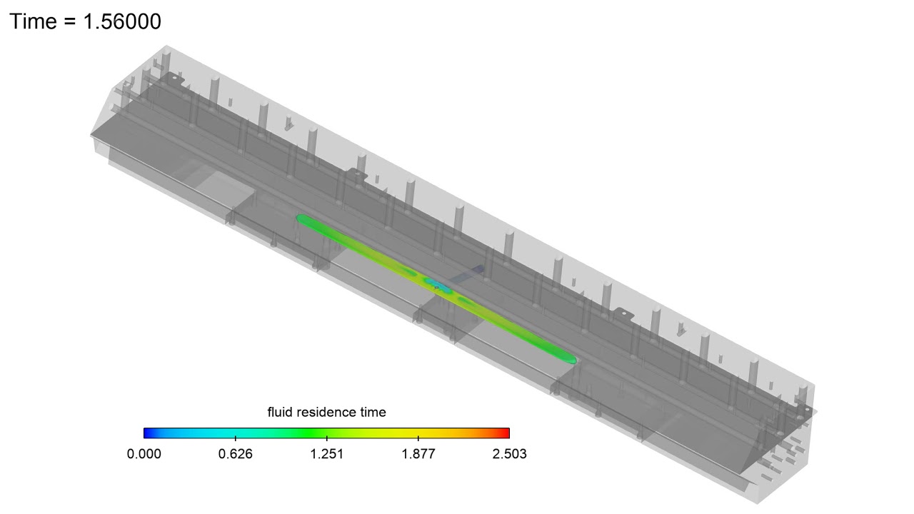
This FLOW-3D simulation, courtesy of 3M, shows the fluid residence time inside the internal cavity of a slot die. The design of the slot die is very important to the success of the coating process, and is specific to the rheology of the coating fluid.
