



FLOW-3D HYDRO Playlist
0:21
0:11
0:21
0:16
0:24
0:21
0:34
0:21
0:48
0:24
0:38
0:24
0:33
0:19
0:25
0:27
0:31
0:21
0:52
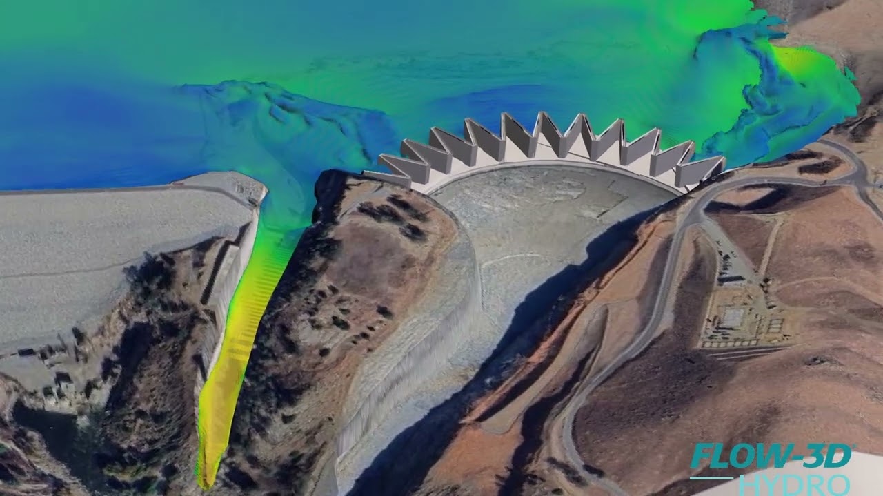
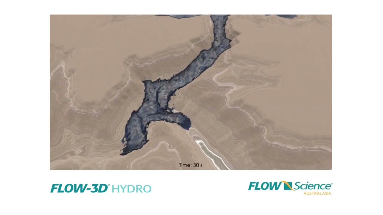
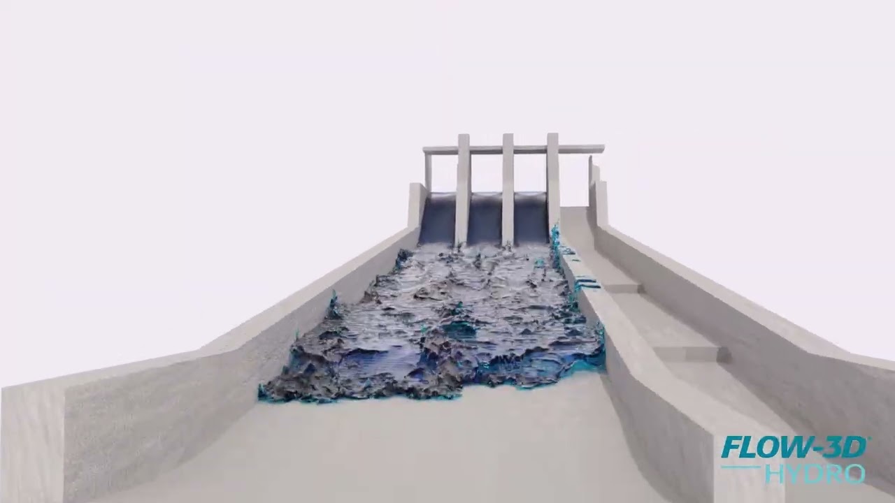
This is a FLOW-3D HYDRO simulation of the Isabella Lake Dam, which features a labyrinth weir. It was created using 3D geometry made publicly available by the USACE Sacramento District. This was done to demonstrate the FLOW-3D POST rendering capabilities, first showing a combination of satellite map texture on the terrain data with velocity field, then using ray tracing for realistic rendering.
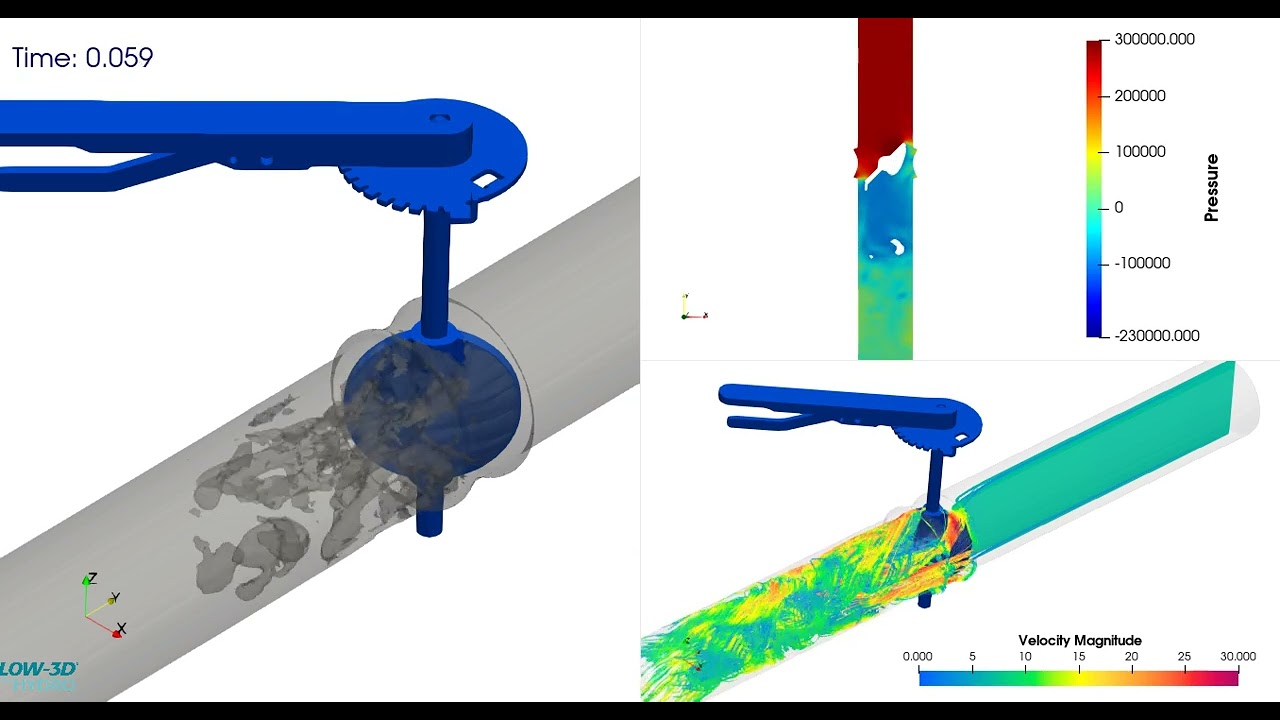
This FLOW-3D HYDRO simulation of a butterfly valve shows cavitation occurring after the valve. By activating FLOW-3D HYDRO‘s cavitation physics model, the void (vaporized water bubble) is captured in real time. On the right side, we also see the pressure distribution (top) and the velocity field with streamlines (bottom).
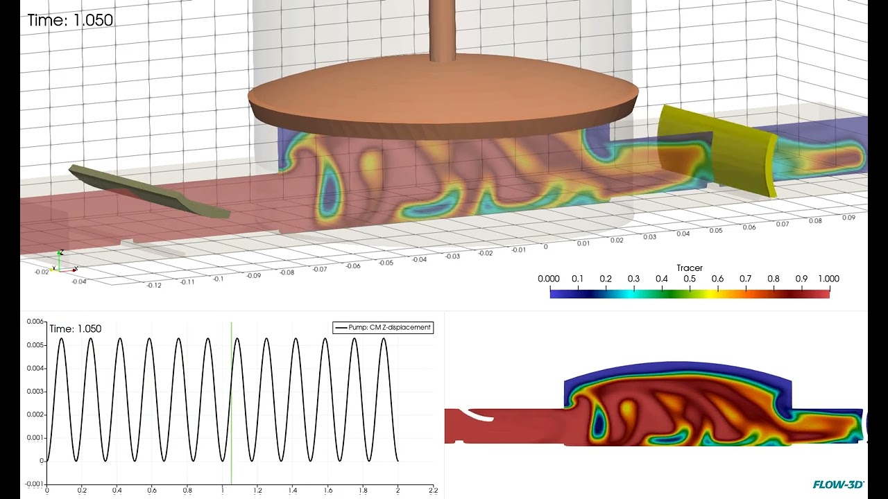
This simulation of a reciprocating pump features FLOW-3D HYDRO‘s General Moving Objects (GMO) physics model. The piston movement is prescribed, while the upstream and downstream check valves’ movements are coupled with the fluid, with rotational constraints. The simulation shows how the fluid is drawn in through the upstream check valve and pushed through the downstream check valve, ensuring one-way flow. A tracer (scalar) was added to the simulation to show the fluid behavior.
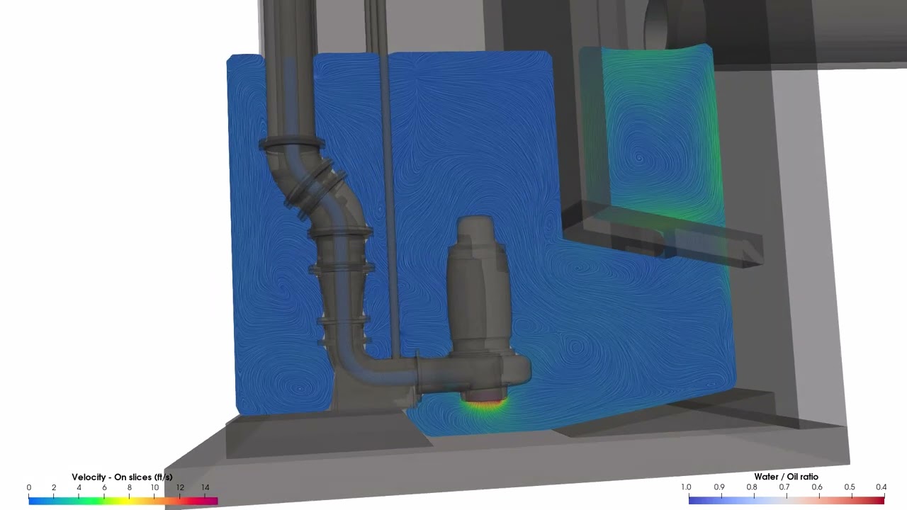
Here’s a simulation from a wet well improvement project by McKim & Creed. The goal of this project was to reduce floating oil & grease buildup, while maintaining good pump intake conditions. FLOW-3D HYDRO was used to simulate the oil & grease behavior in the water using the Disperse Multiphase Flow model. This video showcases 2D slices to analyze the velocity field and streamline around the pump intakes.
This video shows a comparison between the numerical and the physical world. It features a lab model of the Santiago Dam done by Verdantas, and the related FLOW-3D HYDRO model developed by GEI Consultants. CFD allows the testing of designs at a 1:1 scale for various operating conditions, extracting information that is sometimes impossible to obtain through physical methods. In essence, physical and numerical modeling approaches are complementary. FLOW-3D HYDRO helps engineers save time and lower costs on physical lab testing by evaluating designs in advance, thus enabling the construction of selected designs with minimal modifications required.
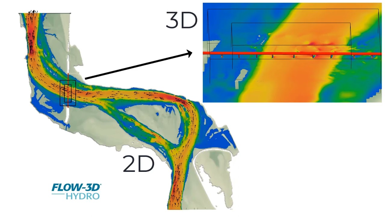
This FLOW-3D HYDRO CFD simulation uses the Hybrid 3D/Shallow Water model to better understand and more efficiently model bridge hydraulics. The simulation fully couples the 3D model with a 2D shallow water model together in one run. The surrounding areas to the bridge were modelled in full 3D, while the upstream and downstream areas of the river were modelled using a 2D shallow water model.
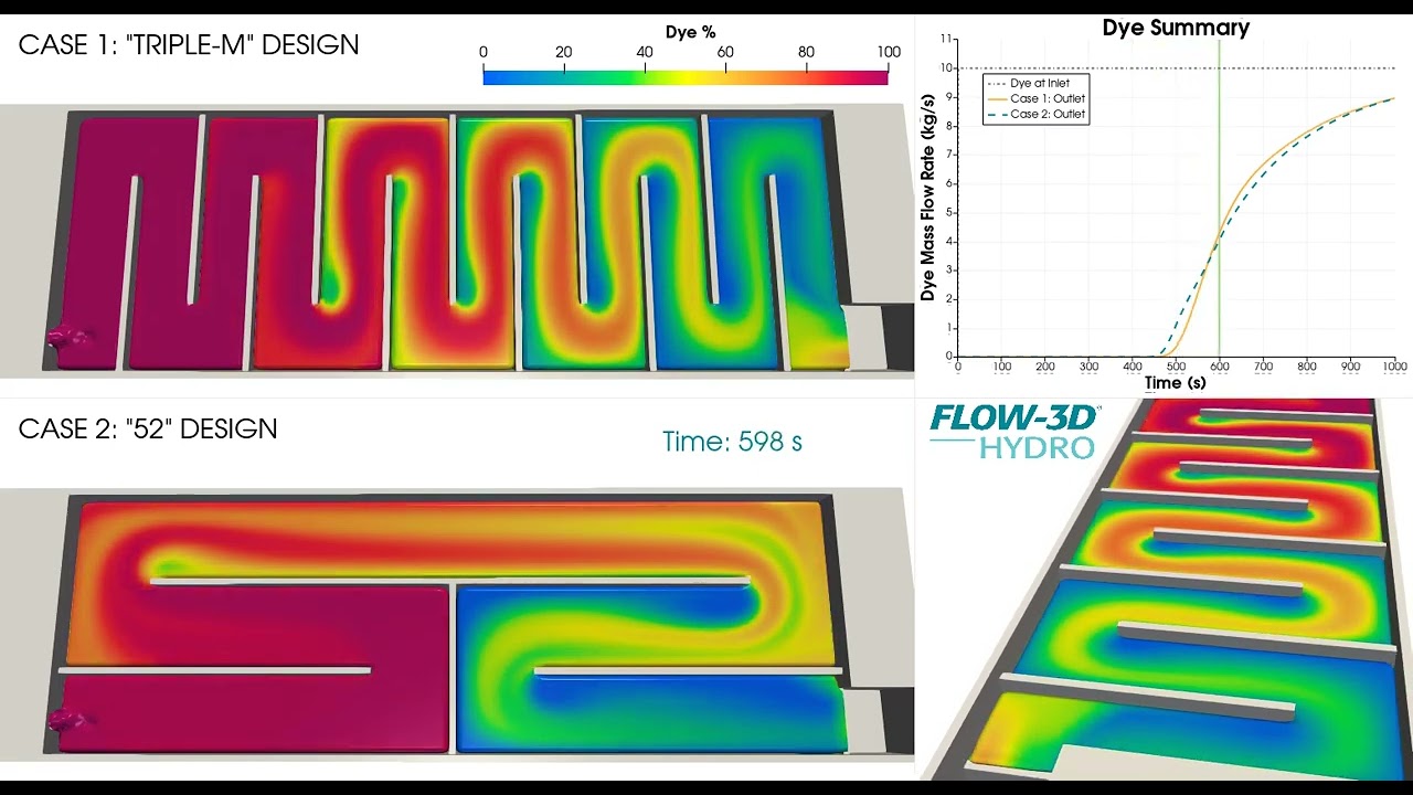
These FLOW-3D HYDRO simulations are comparing two serpentine contact tank designs. A scalar, or tracer dye, is introduced at the inlet of both tanks in order to compare dye distribution as the flow travels through the tanks. This is illustrated by coloring the fluid with the percentage of dye. On the upper right, we have a graph comparing the dye content at the outlet for each design, also known as a residence time distribution (RTD) curve.
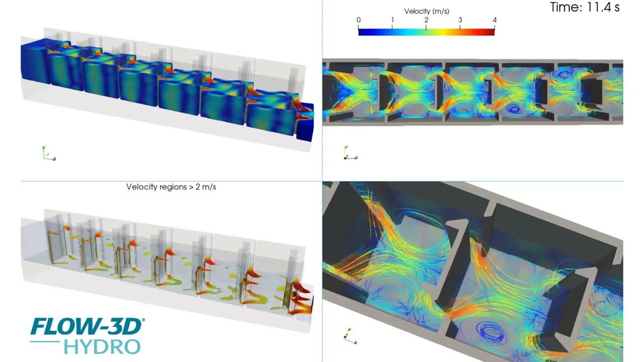
Fish passages need to be designed to accommodate the local fish species and each species will have its own set of hydraulic characteristics to design for. FLOW-3D HYDRO can help you assess whether your fish passage will be suitable for all of your targeted fish species by identifying key velocity zones, as shown in the lower left corner of the video where the high velocity regions are highlighted. It can also help you inspect flow patterns throughout the structure, as illustrated by the velocity streamlines on the right side of the video.
Dam break simulations present a difficult challenge when you want to capture the intricate details of a dam release to get an accurate representation of the flow hydrograph, but have a very large runout extent to consider. In FLOW-3D HYDRO, dam break studies are a great application for its hybrid meshing capabilities. You can create a two-dimensional (2D) depth-averaged mesh for the downstream extents, but also combine that with a detailed three-dimensional (3D) mesh around the dam break location. This can all be done in the same simulation as illustrated by this example video. A 3D mesh is positioned around the initial dam break location, but the upstream and downstream river extents are handled with a 2D mesh, helping you reduce your simulation times and hardware needs.
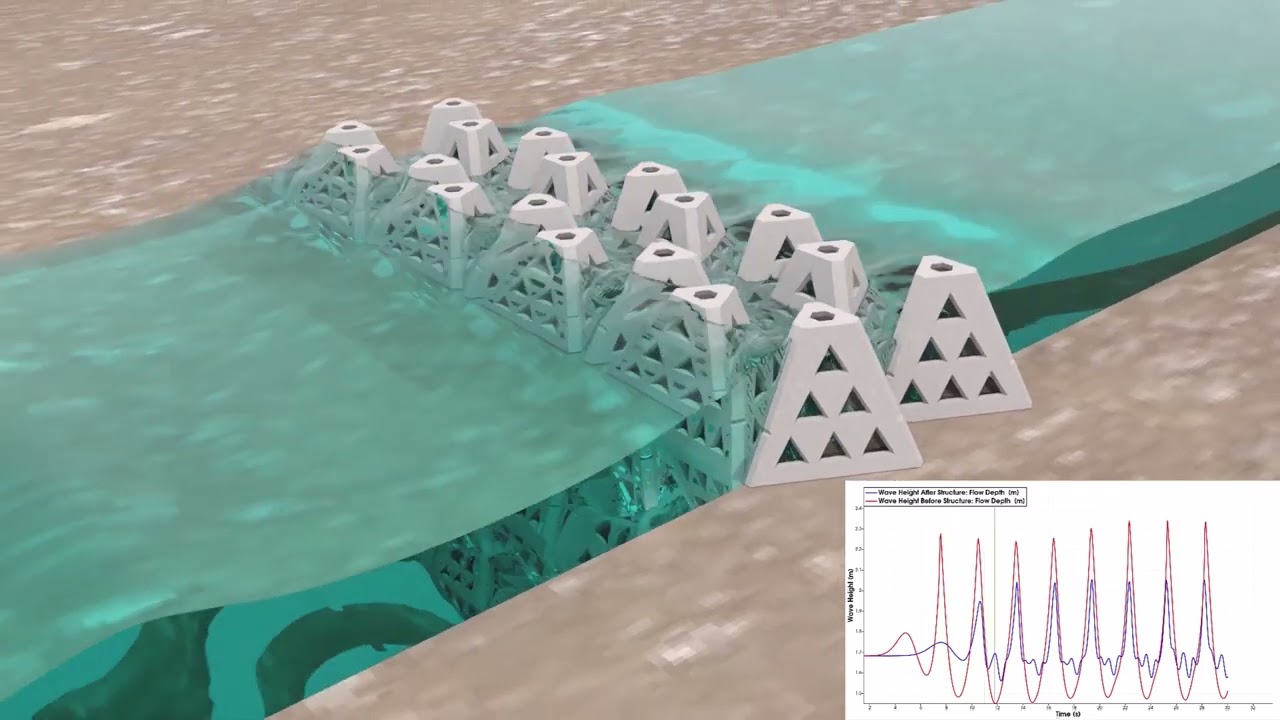
Living shorelines are nature-inspired solutions that can help reduce wave energy and resulting erosion in coastal areas. They have an added benefit of promoting biodiversity, often acting as artificial oyster reefs! FLOW-3D HYDRO is a great tool to evaluate wave energy reduction performance of such structures. This simulation is showcasing the WAD® product from Living Shoreline Inc. We see the wave attenuation, first with ray-tracing, but also with a colormap showing flow depth. As we see with the graph, there’s 65% wave height reduction after the reef.
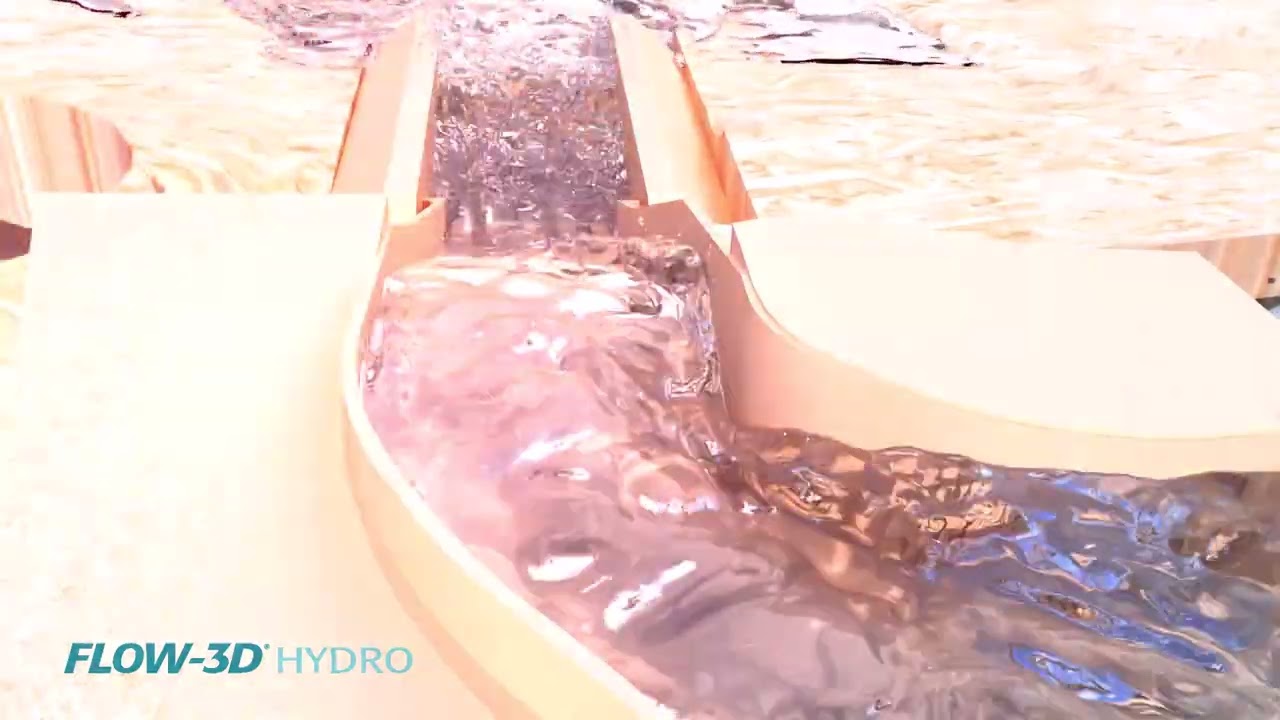
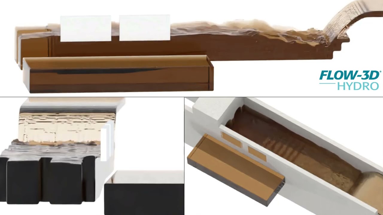
This FLOW-3D HYDRO simulation shows realistic rendering of water, flowing in as a nappe into a stepped chute. The tank overflow is then discharged via two sliding gates, modeled as vertically moving objects.
The San Francisco Department of Public Works used FLOW-3D HYDRO as part of an ongoing project to reduce recurrent flooding within their combined sewer system. As part of this project, the City proposed the upgrade and replacement of existing box sewers at critical junctions in the collection system network that were limiting upstream capacity. Because of unique site constraints and design requirements, 3D CFD simulations with FLOW-3D HYDRO were used to evaluate the performance of these proposed box sewer upgrades.
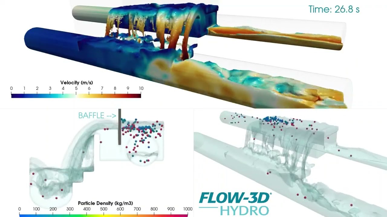
In combined sewer systems, baffles can be a simple, low-cost, low-maintenance option for preventing floatable debris from entering waterways during a sewer overflow event. However, for a baffle to be effective, having a good understanding of the underflow velocities is important in its ability to prevent floatables debris from being drawn under the baffle. FLOW-3D HYDRO provides an efficient way to analyze the hydraulics at diversion structures and inspect your baffle’s underflow velocities. As this video shows, you can even release floatable particles to represent floatable debris and estimate the retention of floatable materials within your diversion structure.
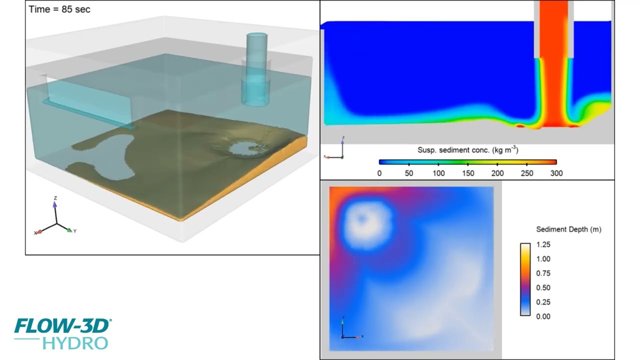
While FLOW-3D HYDRO‘s sediment transport physics is often applied to scour and erosion applications, it can also be useful for settling applications. In this treatment process example, sediment-laden flow enters from the top inlet pipe, and coarse grit particles deposit along the tank bottom. The “clean” water is then discharged via the weir in the side wall. For this application, the client was interested in the deposition patterns within the tank to assist with tank cleaning and maintenance schedules.
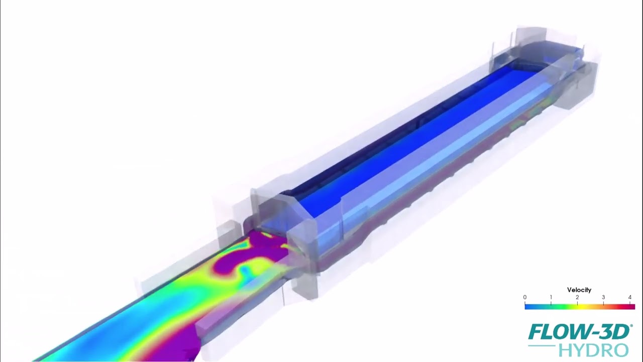
This FLOW-3D HYDRO simulation of a lock in the Champlain canal demonstrates the downstream flushing strategy designed to keep invasive species out of the lock. This animation was created with FLOW-3D POST, and features 2D slices to show the velocity field downstream of the lock. Courtesy of AnchorQEA.
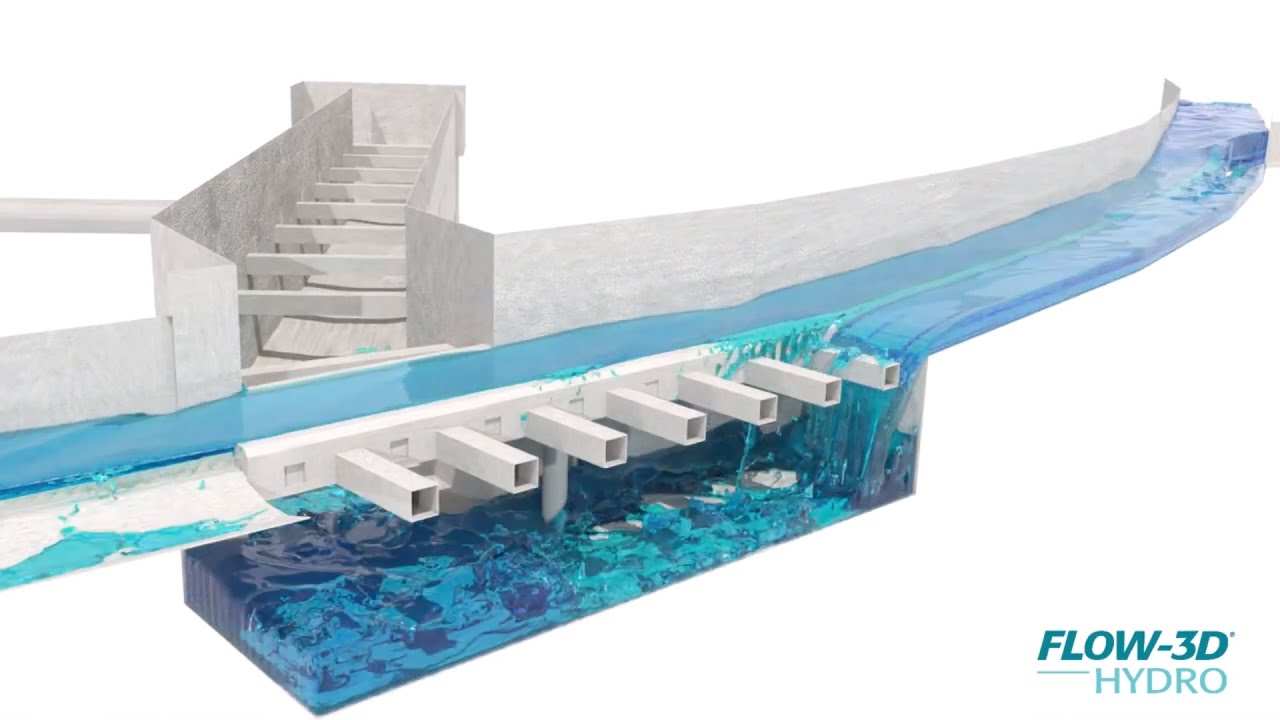
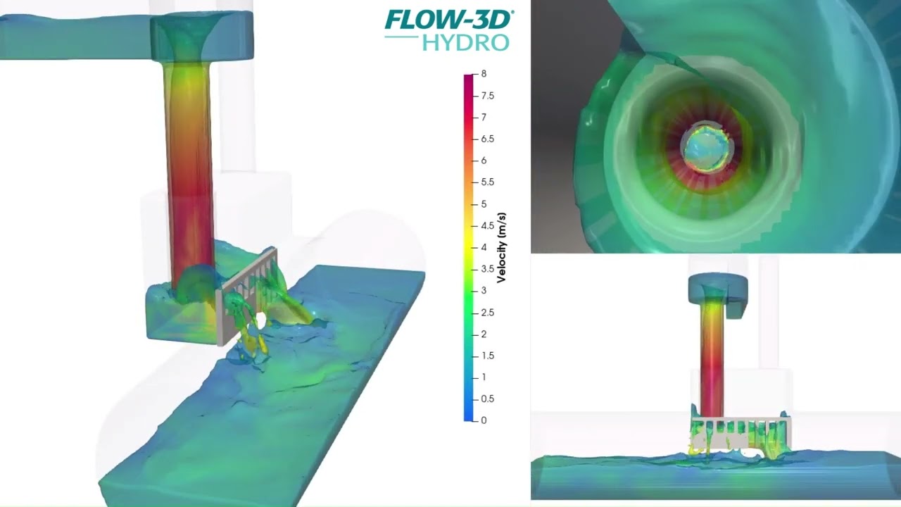
Dropshaft structures are designed to take stormwater from one elevation to another while dissipating energy and allowing air to escape. Such complex hydraulics can be modeled accurately using FLOW-3D HYDRO. In this vortex dropshaft example, the intake geometry induces a spiral motion as water flows down the shaft into a stilling basin. Energy is dissipated in that basin before water flows through a screen into the lower conduit. Alternating between the velocity field and realistic rendering is a great way to share information with stakeholders.
Advanced visualization capabilities allow engineers to communicate complex hydraulic analysis results effectively by integrating multiple data sources into compelling presentations. This FLOW-3D HYDRO visualization demonstrates post-processing workflows in FLOW-3D POST, combining CFD simulation results with 3D scan data of the terrain and CAD geometry of the spillway structure. The rendering showcases ray tracing capabilities for realistic visualization followed by velocity field analysis. FLOW-3D POST enables engineers to create high-quality visualizations that integrate simulation results with real-world site data for stakeholder presentations and technical analysis.
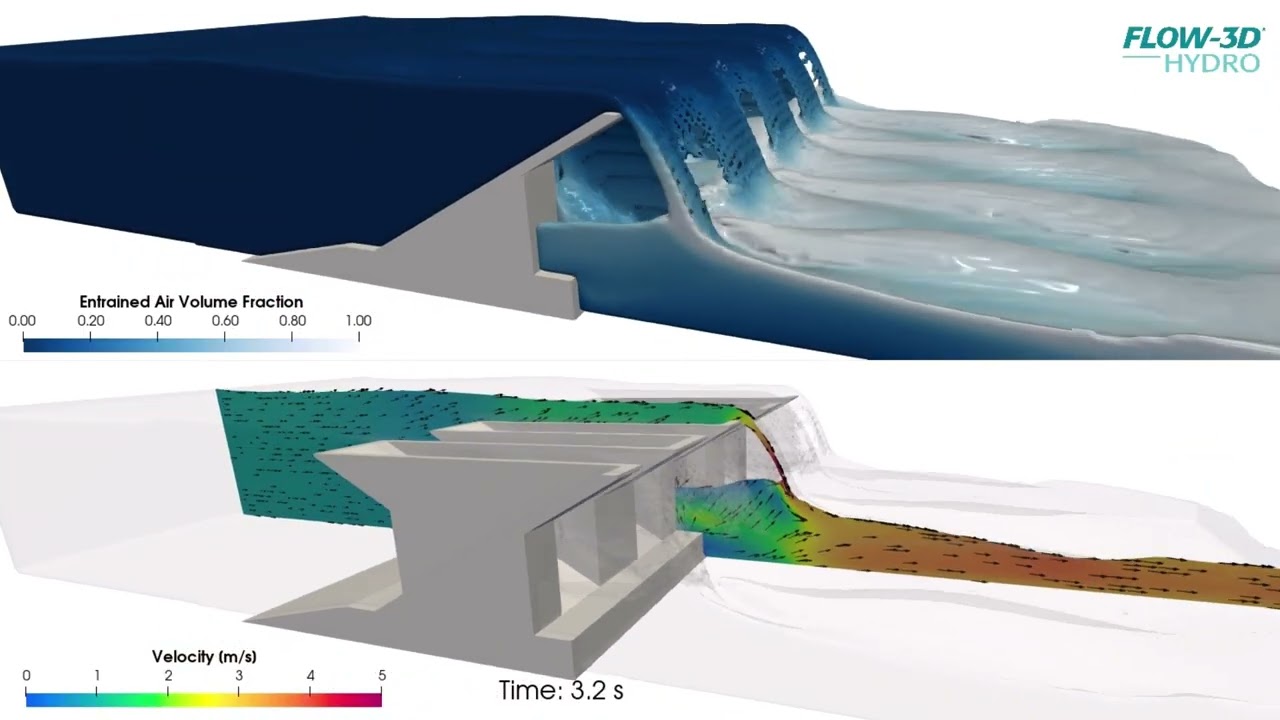
Piano key weirs (PKW) are complex non-linear spillway structures that increase discharge capacity within constrained footprints, making accurate hydraulic analysis essential for design optimization. This FLOW-3D HYDRO simulation demonstrates flow through a PKW geometry, showcasing both realistic rendering capabilities and technical visualization options. The video presents realistic ray-traced rendering alongside 2D section cuts colored by velocity magnitude with vector displays, illustrating how engineers can extract useful technical information from simulation results. CFD modeling helps dam professionals analyze complex spillway geometries and optimize PKW designs for both existing and proposed projects.
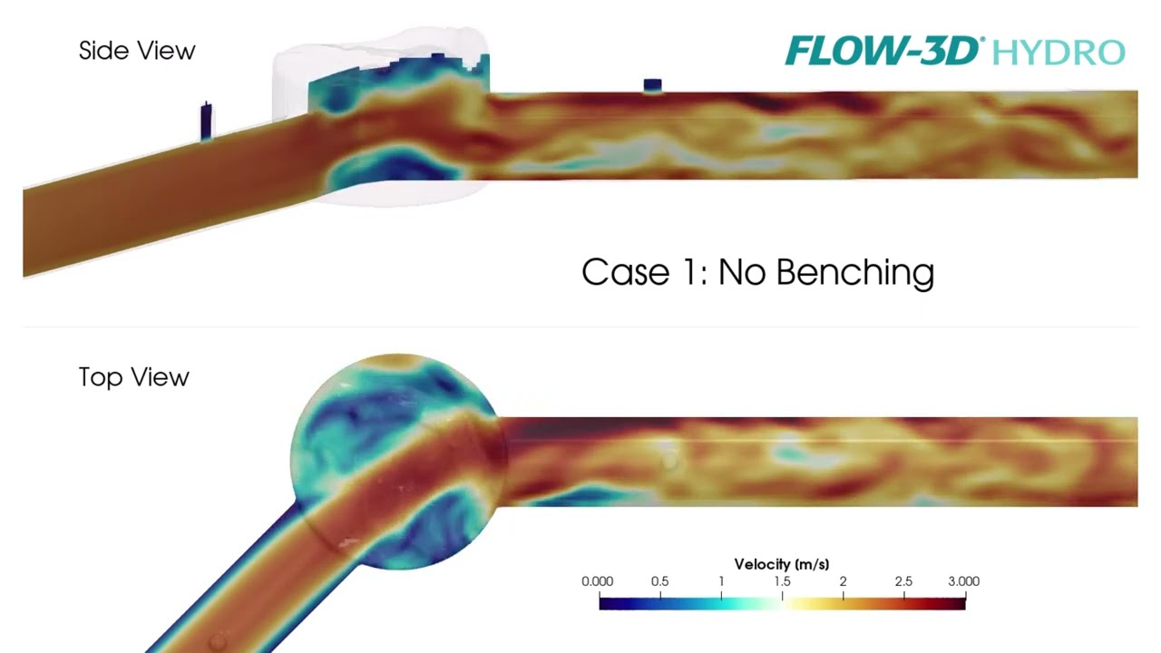
Understanding the hydraulic losses at junction manholes can be very important when designing sewer infrastructure and assessing hydraulic grade lines in the system. Three-dimensional computational fluid dynamics modeling can help you estimate these losses and evaluate design alternatives. This FLOW-3D HYDRO example compares three design options for a junction manhole: 1) base model with no benching, 2) benching halfway up the pipe diameter, and 3) benching that goes above the pipe crown. For this particular flow rate and downstream water level, the half-pipe benching results in a head loss reduction of 28% while the taller benching case reduces the head loss by 33% when compared to the base case without benching.


