

Die Spray Cooling
The Die Spray Cooling model simulates the spatial variation in the spray cooling to accurately predict the temperature distribution in the die in thermal die cycling simulations. This model explicitly computes the cooling from each spray, instead of assuming a constant heat transfer coefficient across the entire die cavity. The spray area on the die surface is computed and updated constantly due to the movement of the spray nozzles. The model also takes into account the blocking of the fluid being sprayed, and thus the effect on cooling, due to the spray angle and the shape of the die surface. The new model provides accurate temperature distributions on the die surfaces with reliable and realistic input parameters that help engineers to better design and optimize the cooling process to eliminate hot spots.
Spray Area Computation
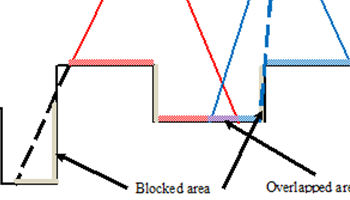
The influence of the shape of the die surface and the position of the spraying nozzles on the spray cooling is taken into account in the new model. As shown in the figure below, some areas under the spray on the die surface are blocked, and some areas are overlapped by two or more sprays. These areas are computed and identified using a ray tracing algorithm to distinguish the different spray cooling effects. The spray area can be visualized in FLOW-3D POST, along with other properties, such as the total spray time and total heat removed per unit area by the spray cooling.
Heat Transfer Coefficient Determination
Spray cooling mechanisms are complicated, and the spray cooling heat transfer coefficient (HTC) depends on many variables such as spray shape, coolant flow rate, spray pressure, mold temperature, spray angles, and spray distance. To simplify the spray cooling HTC calculation, for every spray surface element, the HTC is computed by multiplying the base HTC by dependence factors, for example for a conical spray,
$latex \displaystyle HTC=HT{{C}_{0}}(T)\cdot {{f}_{d}}(d)\cdot {{f}_{b}}(\beta )\cdot {{f}_{e}}(\varepsilon )$
where
- HTC0 is the base spray heat transfer coefficient when the nozzle sprays on the mold from a specified distance. The base heat transfer coefficient is dependent on the spray cone characteristics, spray medium, and spray pressure, etc., and is a function of the mold surface temperature.
- fd is the distance d dependent factor function.
- fb is the spray angle β dependent factor function.
- fe is the spray angle (between the surface normal and the spray direction) ε dependent factor function
The meaning of the spray distance d, and spray angles β and ε are shown in the picture below.
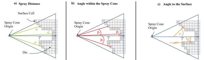
The base heat transfer coefficient and the dependence factor functions can be curve fitted from experimental measurements, derived from theory, or from experience. If the sprays are not conical in shape, the dependence factors could be different.
Spray Nozzles Definition
The spray nozzles are grouped into banks. Nozzles in the same bank have the same characteristics, such as spray cone angle. They also have the same spray medium temperature, spray to the same group of die components, share the same status control table, and have the same heat transfer coefficient functions.
All spray nozzle banks are virtually mounted on the same robot arm. The translational and rotational movement of the robot arm can be specified in FLOW-3D CAST. If the motion data is saved in an external file, it can be imported from or linked to an external file. The capability of importing or linking external files significantly simplifies the input because the control data programmed for the spraying machine can be directly used for the model.
Nozzle properties can be directly read in from a nozzle database. Since the heat transfer coefficient functions are dependent on the spray cone characteristics, including the spray cone angle, they are all part of the nozzle properties included in the nozzle database. If nozzle is not defined in the database, its properties can be directly input. The heat transfer coefficient functions can be constants or can be defined as tables. Similar to other table inputs, the data can be linked to external files. If the same nozzle is used often, its properties can be easily added to the nozzle database, similar to adding new material in the material database.
For each nozzle, the spray origin and end coordinates, or spray directions need to be defined. If the nozzle locations are pre-designed and the data is available, or the number of nozzles is relatively large, they can be read in from external files. If the number of nozzles is less the locations can be picked interactively and typed in a tabular form.
Sample Results
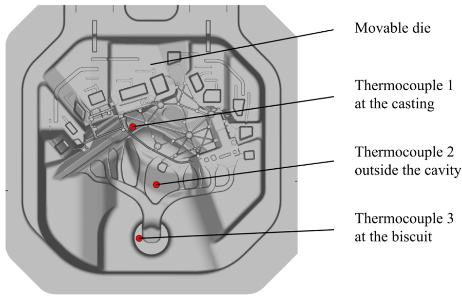
A case study was carried out to demonstrate the capability of the new model, and the importance of explicitly simulating the die spraying process. It is based on the production of a vehicle structural part with large dimension and thin wall thickness. Three thermocouples are placed inside the die surface of the ejector die. The positioning is shown in the following figure. The first thermocouple is placed in the die surface at the casting area. The second thermocouple is defined outside the cavity. So there will be no contact to the melt, but there will still be cooling during the spraying process. The third thermocouple is at the biscuit, a hot spot inside the die.
The simulation is based on 5 cycles, where each cycle is defined by four segments; solidification, ejection, spray-cooling, and dwelling. In the implicit die spray cooling simulation, where a constant heat transfer coefficient across the entire die cavity is assumed, it is always hard to estimate the average times for spray, since no real process values can be used. In this case study, the average times are estimated and adjusted so that the temperature at thermocouple 1 matches the measurement. On the contrary, for the new spray cooling model, where cooling from each spray nozzle is explicitly simulated, the realistic spraying process includes all time values, which can be directly transferred into the simulation. This is one of the advantages of the new die spray cooling model.
The first animation below shows the spray area on the die surface during spray cooling. The second animation shows the die surface temperature during the spray cooling at the fifth cycle. The effect of global spraying and hotspot spraying can be clearly seen and identified.
Spray area during spray cooling. Simulation courtesy of Audi AG.
Die surface temperature at the fifth cycle of spray cooling. Simulation courtesy of Audi AG.
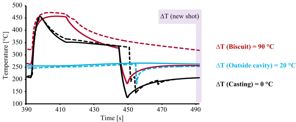
The temperatures of the three thermocouples during the fifth cycle are plotted in the following figure. The solid lines indicate the results from the implicit model and the dotted lines are from the new die spray cooling model. The temperature differences in the three thermocouples at the end of the cycle are also shown. It can be seen that in order to match the temperature at the thermocouple 1, in the implicit model, the biscuit area is over cooled, which results in a 90 °C difference in die temperature at the thermocouple 3, which is a dramatic difference. For die casters the temperature in the biscuit is a very sensitive temperature in die casting process. The temperature difference outside the cavity (thermocouple 2) at the end of the cycle is 20 °C. These values decide in a real process if good quality is produced or if the casting solders to the die during ejection. The explicit simulation of the die spray cooling process is critical in predicting accurate die temperature distribution.
FLOW-3D CAST‘s die spray cooling model lets users model all facets of die preparation, taking into account the influence of the shape of the mold surface and the position and movement of the spray nozzles. It can accurately predict the exact temperature distribution on the die surface with reliable and realistic input parameters for thermal die cycling simulations. This helps metal casting engineers to better design and evaluate the internal cooling structure of the die, and the spray cooling parameters.
References
- Müller, et al., A die spray cooling model for thermal die cycling simulations, Transactions of NADCA 2015 Die Casting Congress & Exposition, Indianapolis, T15-101, 201
