What’s New – FLOW-3D HYDRO 2022R1
The new 2022R1 versioning of FLOW-3D products reflects Flow Science’s adoption of a synchronized release naming convention for FLOW-3D, FLOW-3D CAST and FLOW-3D HYDRO. 2022R1 represents the transition to a unified code base for FLOW-3D products. This important evolution will allow users access the latest developments as soon as they are ready, at a more frequent product release pace.
The FLOW-3D HYDRO 2022R1 release features an extension to the FAVOR™ method called detailed cutcell representation, new dissolved oxygen and axial pump models, extensions to Active Simulation Control capabilities, tabular properties which allow users to specify complex property dependencies based on two independent variables, and additional numerics features such as a VOF-to-particle development to improve mass conservation for fluid regions subject to breakup.
Detailed Cutcell Representation – An Extension to FAVOR™
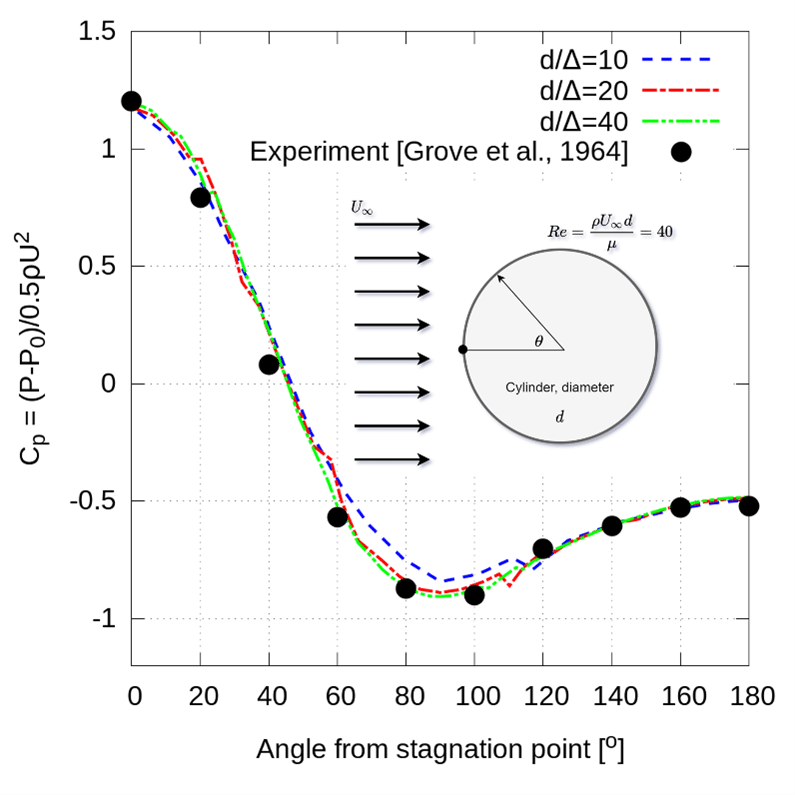
The FAVOR™ method represents solid geometry using area and volume fractions on a regular, Cartesian grid. It enables FLOW-3D HYDRO to efficiently simulate flow through and around complex geometry without resorting to unstructured body-fitted meshes. One challenge for the FAVOR™ method is computing accurate wall shear stresses along solid surfaces that do not align with a mesh plane. An extension to FAVOR™ called detailed cutcell representation greatly improves the calculation of wall shear stresses, resulting in significant improvements in the calculation of drag forces on solid surfaces as well as pressure drops along surfaces and in channels.
Learn more about the advanced numerics as well as validations of the detailed cutcell representation.
Dissolved Oxygen Model
Dissolved oxygen in water plays an important role in natural and manmade habitats. Acceptable levels of dissolved oxygen is a key indicator of water quality. In wastewater treatment plants, oxygen feeds bacteria that break down contaminants. FLOW-3D HYDRO‘s new dissolved oxygen model is coupled with the air entrainment, drift-flux and dynamic bubble size models, creating a consistent approach to modeling air bubble and dissolution dynamics. The mass transfer coefficient between the bubbles and water can be specified in one of three ways: as a user-defined constant, through a “clean” bubble assumption using Higbie’s model, or through a “dirty” bubble assumption which accounts for the effects of surfactants on oxygen dissolution.
In this simulation, oxygen bubbles are injected from two diffusers at the bottom of the container and allowed to rise in water. As the bubbles rise, oxygen dissolves into water. The image on the left shows the concentration of dissolved oxygen in water. The image on the right shows the water velocity which is induced by the rising oxygen bubbles.
Expanded Controls for Active Simulation Control
Active Simulation Control (ASC) is very useful for controlling simulations based on flow information at probes. In this release, ASC has been expanded to allow additional controls based on flow information from general history data, flux surfaces, and sampling volumes.
One of the advantages of flux surfaces and sampling volumes over point probes is that they can provide information that is averaged over a surface or a volume rather than point-based. In some situations, surface-based and volume-based information can be more representative of the behavior of interest in simulations.
With this new capability, users can:
- Terminate a simulation when the temperature in a control volume exceeds or falls below a critical value.
- Open and close valves when the mass or volume of fluid in a control volume reaches the specified values.
- Control the filling rate from a nozzle based on the turbulent energy in a sampling volume.
- Control the output frequency based the average velocity on flux planes.
- Terminate a simulation when fill fraction in a sampling volume reaches the value specified by the user.
This example represents a sludge decanter that models a mixture of water and sludge entering a decanter and separating. Water is allowed to flow in and out at the back side of the decanter to maintain a relatively fixed level in the decanter. A sampling volume in the bottom of the decanter is used to measure the amount of sludge captured at the bottom. When the sludge mass in the sampling volume reaches 200 kg, a valve opens to release the sludge. The valve closes when the sludge mass drops below 180 kg.
Axial Pump Model
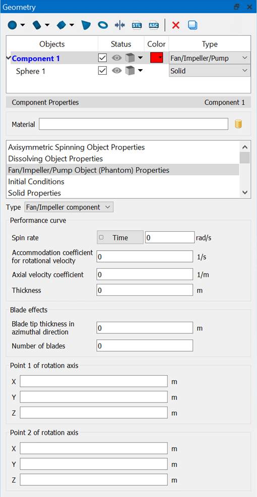
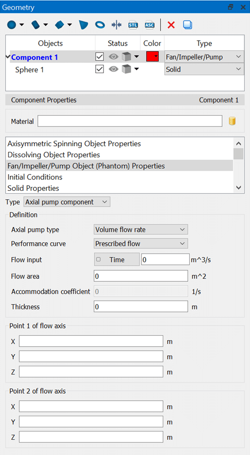
FLOW-3D HYDRO’s new axial pump model allows users to mimic the net effect of an axial pump in their simulations. There are two options with respect to the pump behavior. The first option is to prescribe either a volumetric flow rate or a flow velocity through the pump so that the fluid is moved at the specified rate. This option is appropriate when an operating flow rate is provided for the pump. The second option provides a more complete definition of the pump operation based on a pump performance curve. In this case, the user can define a linear approximation of the pump’s performance curve so that the flow rate through the pump will depend on the pressure drop across the pump. In this configuration, the typical behavior of a pump is represented, whereby the flow will slow down and eventually stall as a reverse dynamic head builds up and pushes back against the pump operation.
In the GUI, users can define component-based pumps using a dynamic view based on Fan/Impeller or Axial pump components, where the flow rate is prescribed using a momentum source.
Tabular Properties
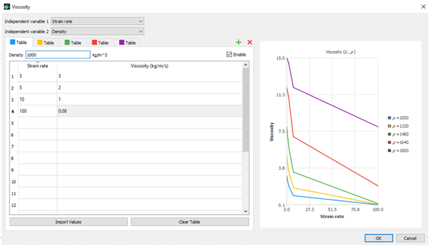
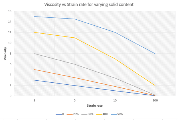
Material properties such as viscosity and surface tension can be dependent on flow conditions such as temperature, density, strain rate, or user-defined scalar quantities representing things like a contaminant concentration. Fitting these properties to functional forms can require complex curve-fitting, especially when the properties are dependent on more than one independent variable. The new tabular properties feature in FLOW-3D HYDRO allows users to define fluid properties in table form with up to two independent variables. For example, surface tension can be tabulated from experimental data to describe complex, non-linear dependencies on contaminant concentration and temperature, or viscosity can be tabulated from experimental data to represent a dependency on strain rate and temperature. Users can input a single variable or two variable dependency in the tabular properties dialog.
Viscosity is defined as a function of both solid content (density) and strain rate. In this example a dense fluid region slides down into a quiescent pool which at time zero is layered with a dense settled fluid region and clear water above.
VOF to Particles
The accuracy and robustness of the sharp-interface tracking VOF methods in FLOW-3D HYDRO have been enhanced by combining them with fluid particles. The new particle species, called VOF particles, are used in place of the VOF function to track small fluid ligaments and droplets in the computational domain, achieving better conservation of fluid volume and momentum.
Higher time steps size can also be expected in gravity-controlled processes. The VOF fluid is automatically converted to VOF particles at certain times and locations when certain conditions are met. The particle motion is then calculated using the Lagrangian particle model and the particles are converted back to the VOF representation upon reentering the fluid.
Time-dependent Valves
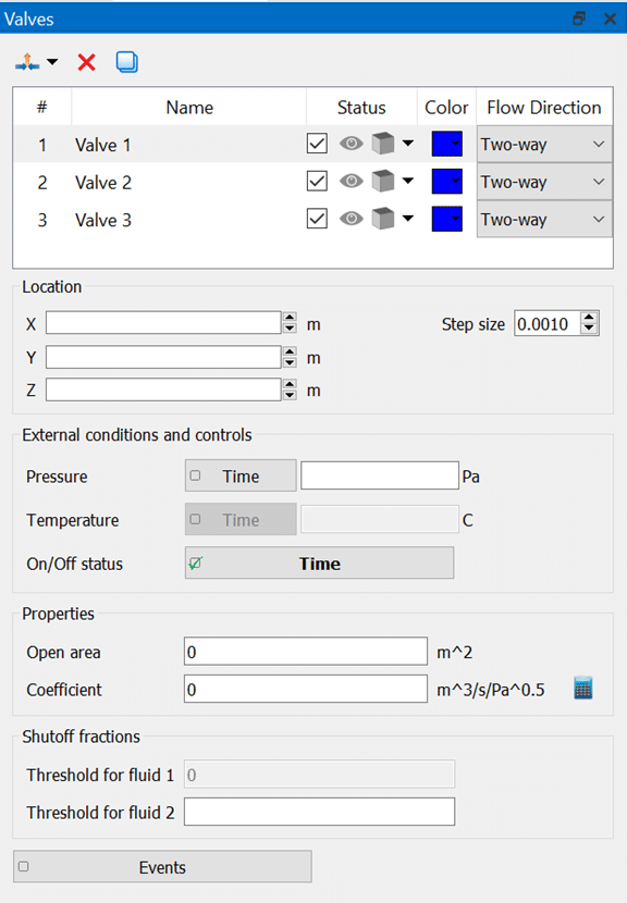
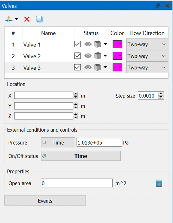
Valves may be used in water transport simulations where it is vital to maintain adequate pressures to support structural stability. Valves can now be controlled based on time. This feature is useful for representing valves that are activated at specified times in a defined control sequence to determine system operating characteristics.
