


Conveyance Infrastructure

0:27

0:23
0:21

0:33


0:21

0:22
0:47


0:40
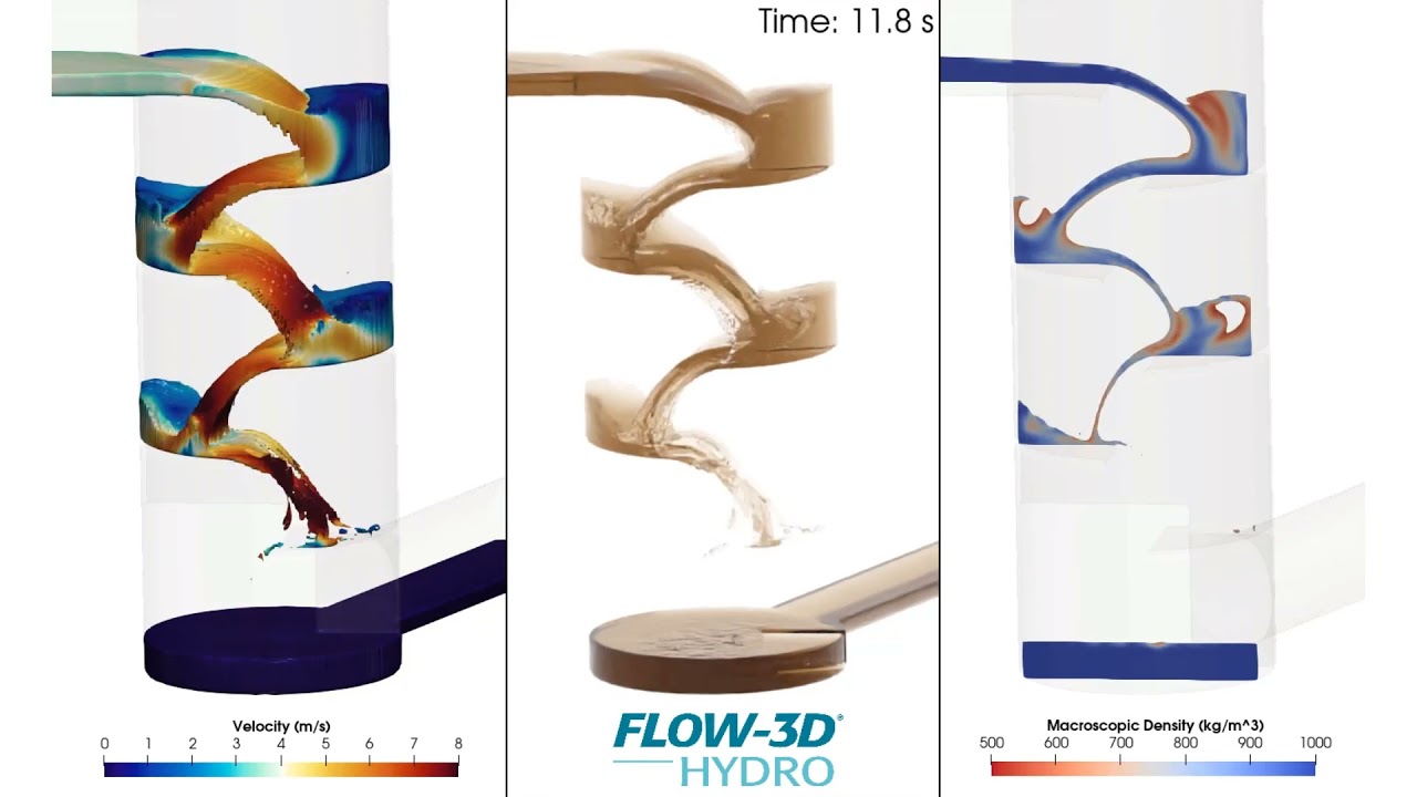
Dropshaft structures are designed to take stormwater from one elevation to another while dissipating energy and allowing air to escape. Such complex hydraulics can be modeled accurately using FLOW-3D HYDRO. In this vortex dropshaft example, the intake geometry induces a spiral motion as water flows down the shaft into a stilling basin. Energy is dissipated in that basin before water flows through a screen into the lower conduit. Alternating between the velocity field and realistic rendering is a great way to share information with stakeholders.
The San Francisco Department of Public Works recently used FLOW-3D HYDRO as part of an ongoing project to reduce recurrent flooding within their combined sewer system. As part of this project, the City proposed the upgrade and replacement of existing box sewers at critical junctions in the collection system network that were limiting upstream capacity. Because of unique site constraints and design requirements, 3D CFD simulations with FLOW-3D HYDRO were used to evaluate the performance of these proposed box sewer upgrades.
Baffle drop shafts transport storm water to underground tunnels for storage and transport. FLOW-3D HYDRO can be used to compare drop shaft design elements such as shaft diameter and baffle spacing, which affect the flow velocity, amount of entrained air, and other flow features.
In combined sewer systems, baffles can be a simple, low-cost, low-maintenance option for preventing floatable debris from entering waterways during a sewer overflow event. However, for a baffle to be effective, having a good understanding of the underflow velocities is important in its ability to prevent floatables debris from being drawn under the baffle. FLOW-3D HYDRO provides an efficient way to analyze the hydraulics at diversion structures and inspect your baffle’s underflow velocities. As this video shows, you can even release floatable particles to represent floatable debris and estimate the retention of floatable materials within your diversion structure.
In this simulation using FLOW-3D HYDRO, you can see streamlines showing a 3D internal flow pattern in a hydraulic structure. The streamlines, colored by the water velocity, highlight the details of the solution in a single view, from the smooth flow upstream of the weir to the complex vortices forming around the plunging jet.
While most of your FLOW-3D HYDRO modeling is done using its efficient one-fluid volume of fluid approach, there are situations where using the two-fluid approach is necessary. In this vortex drop shaft example, understanding the airflow passing up the air vent and drop shaft is critical in the design of the drop shaft. The video below displays the contours of the water, but the airflow in the void regions is also being modeled for this example.
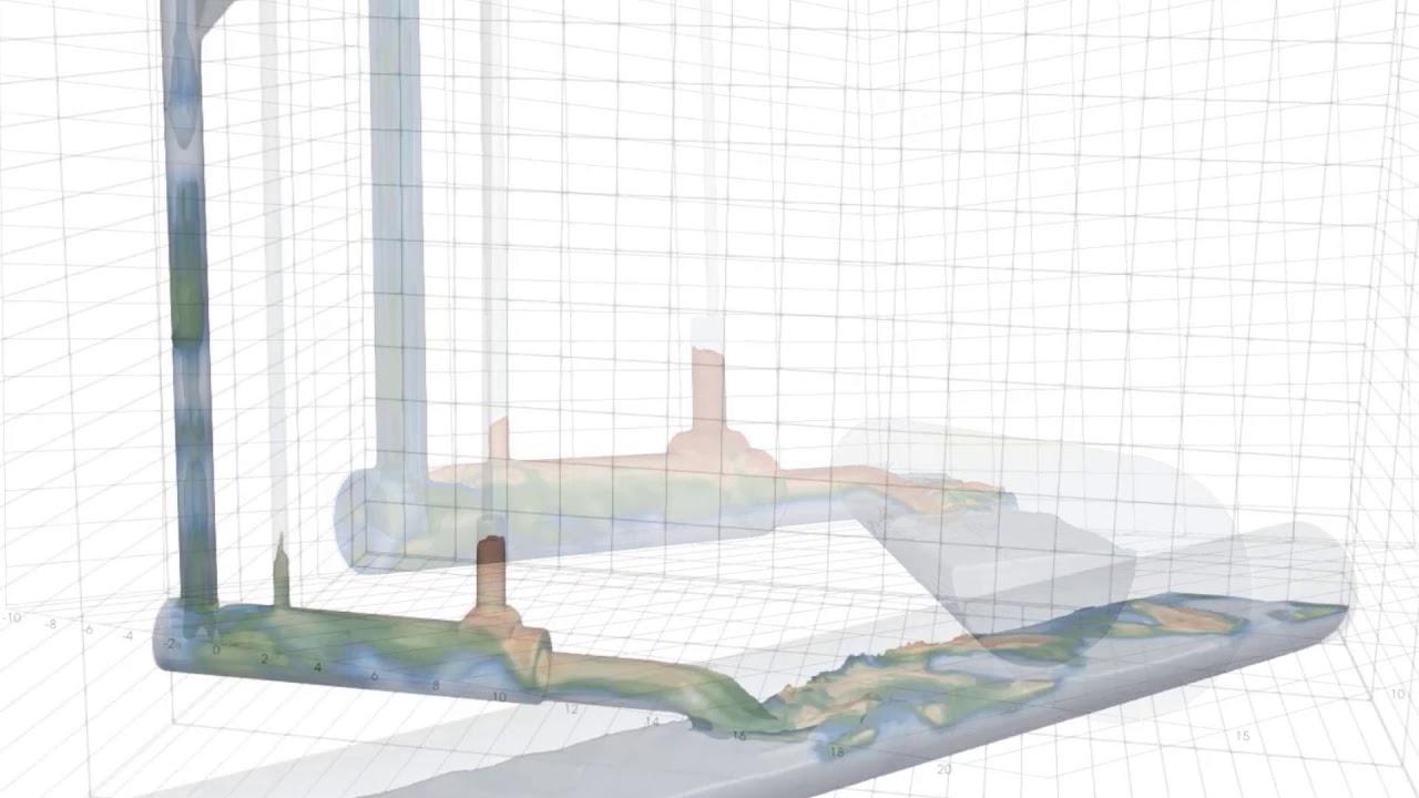
Flow splitters, such as the one shown here, consist of specifically designed elements such as pipes, orifices and weirs and are often used to redirect flows in stormwater conveyance structures/systems. FLOW-3D HYDRO simulations can be used to understand the hydraulic behavior and performance of such systems under various operational flow rates.
Under certain flow conditions tangential dropshaft are effective by promoting the formation of a vortex core in the dropshaft as the flow is propagated to lower elevations. FLOW-3D HYDRO offers multiple modeling approaches to help engineers model free surface flow characteristics, and evaluate the energy dissipation, downdraft and air entrainment behaviors of the system.
Static screens are used in stormwater and combined sewer overflow applications to screen trash and debris from being discharged into a water body. This FLOW-3D HYDRO example illustrates the behavior of floating debris (released 9 seconds into the model run) as they are trapped beneath the screen during an overflow event. The objects are modelled using FLOW-3D HYDRO‘s general moving object model and incorporate coupled motion between the fluid and objects.
This video, courtesy of IIHR, Wade Trim, and Northeast Ohio Regional Sewer District, shows a comparison of a FLOW-3D HYDRO CFD model of a baffled drop draft structure under wet weather conditions with a physical laboratory model.
Vortex valves are a type of flow control device that operates similarly to an orifice. An advantage of vortex valves is that you are able to maintain a larger diameter opening when compared to a similarly performing orifice, reducing its potential to get clogged with debris during a storm event. Because of the larger opening, the vortex valve passes more flow during the early part of a storm. When the water level rises, a vortex core forms to restrict the flow. This FLOW-3D HYDRO model shows how the vortex valve’s air core develops as the water level rises.
In this simulation of a diversion tank, the moving objects model is used to simulate the opening of a sluice gate, which helps regulate the flow of storm water in a combined sewer overflow (CSO) system.
In addition to simulating erosion, FLOW-3D HYDRO‘s sediment transport physics can be used to evaluate the settling of sediments in suspension. In this stormwater sediment basin example, the inlet flow contains suspended sediment. As sediment settles out of the flow and deposits on the basin floor, the solid geometry is adjusted within the FLOW-3D HYDRO model, as seen in the first bay of the sediment basin. A scalar is also used to visualize the flow patterns through the model domain.
Trapped air pockets within sewer networks can lead to an array of operational and safety issues. One potential safety concern can occur during rainfall events when heavy manhole lids are displaced due to trapped air venting through the manhole opening (also known as a sewer geyser). In this example, the manhole lid is represented as a moving object with six degrees of freedom. As the air pocket works its way from the pipe to the manhole structure, the force of the air and water mixture causes the manhole lid to pop off the structure. CFD modeling can help you investigate your sewer’s trapped air issues and develop mitigation strategies.


