


Water Treatment Playlist

0:16

0:52
0:25

0:16
0:55
0:31
0:29
0:21

0:41

0:27

0:18

0:31

0:19
Here’s a simulation from a wet well improvement project by McKim & Creed. The goal of this project was to reduce floating oil & grease buildup, while maintaining good pump intake conditions. FLOW-3D HYDRO was used to simulate the oil & grease behavior in the water using the Disperse Multiphase Flow model. This video showcases 2D slices to analyze the velocity field and streamline around the pump intakes.
Understanding the hydraulic losses at junction manholes can be very important when designing sewer infrastructure and assessing hydraulic grade lines in the system. Three-dimensional computational fluid dynamics modeling can help you estimate these losses and evaluate design alternatives. This FLOW-3D HYDRO example compares three design options for a junction manhole: 1) base model with no benching, 2) benching halfway up the pipe diameter, and 3) benching that goes above the pipe crown. For this particular flow rate and downstream water level, the half-pipe benching results in a head loss reduction of 28% while the taller benching case reduces the head loss by 33% when compared to the base case without benching.
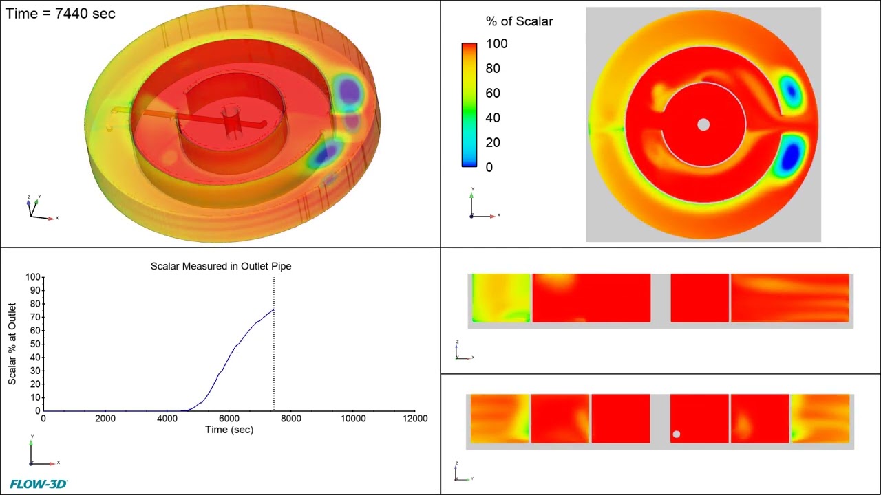
This is a FLOW-3D HYDRO simulation of a circular contact tank with concentric baffles. A scalar is introduced at the inlet in the center and we can see the dispersion as the flow travels through the tank, with the fluid colored to show the percentage of scalar present. The graph on the lower left corner is giving us the percentage of scalar at the outlet pipe, also known as a residence time distribution (RTD) curve. This information can be useful to understand and improve contact tanks designs: making sure there is optimal mixing, no dead zones and no short circuiting. Down the line, improving efficiency helps save on operational costs.
Sanitary Sewer Overflow (SSO) events have negative effects on human health and the environment. Flap gates can be used as constriction flow meters for the estimation of SSO discharge. FLOW-3D HYDRO provides powerful insights into the analysis of fluid-solid interaction. This can be used for direct estimation of flow rate at a specified head differential and flap gate diameter. Additionally, factors like density variations of flap gate cover, the thickness of flap gate cover, angle of flap gate at the opening, hinge point locations, etc. can be considered and tested in FLOW-3D HYDRO. The simulation model is validated by comparing the results with that of the experimental. A good agreement between the results of the FLOW-3D HYDRO model and experimental results can be seen.
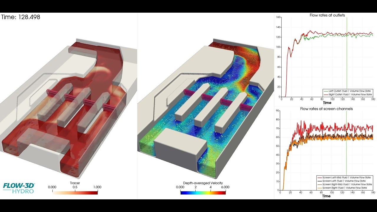
Before designing or constructing modifications to existing infrastructure, FLOW-3D HYDRO can be a valuable tool to investigate hydraulic issues. In this example, an existing screen channel is modeled showing that one of the screens receives more flow than the others, which could lead to increased maintenance or cleaning at the screen. Understanding the existing hydraulic conditions is valuable when designing a solution to the flow distribution issue.
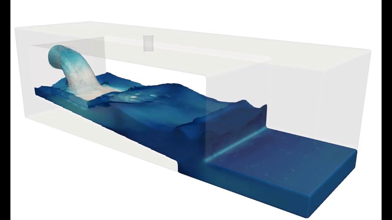
This pre-packaged FLOW-3D HYDRO example of a discharge into a tank uses the Free surface – 2 fluid VOF template available in FLOW-3D HYDRO for users to quickly setup two phase air/water models. Air and water properties, and all the appropriate models and numerical settings are pre-loaded into the simulation, providing a great starting point to model two phase flows, from setup through to post-processing analysis.
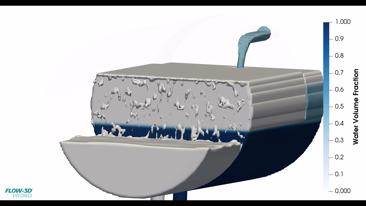
FLOW-3D HYDRO is a great tool to simulate multiphase flows in the field of produced water. This simulation shows a baffled oil-water separator. As we can see, the heavier water phase stays at the bottom (dark blue color), while the lighter oil phase rises to the top (light grey color).
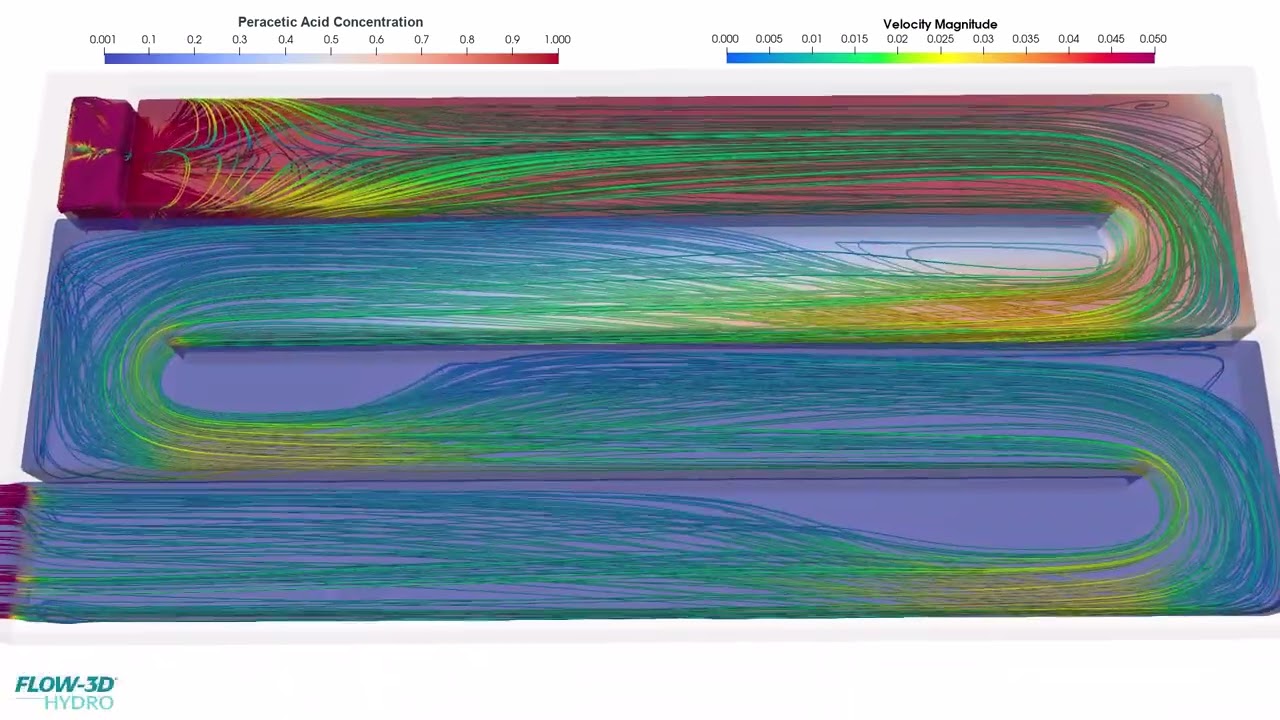
FLOW-3D POST allows you to combine different types of information and create compelling visual assets. In this example of a serpentine contact tank, the streamlines give us information about the flow behavior and velocity. It is interesting to see the turbulence zone on the upper left after the inlet weir. Turbulence is critical for mixing disinfectant in this type of system. Streamlines allow us to easily identify dead zones, recirculation zones and potential flow by-pass. You can see the peracetic acid concentration decreasing as water flows through the contact tank, due to its reacting/neutralizing with pathogens, but also because of natural decay over time. Both of these reactions were modeled in FLOW-3D HYDRO using the reaction kinetics model.
The interaction of solid particulate matter with air bubbles (seen in orange and rising from aerators at the bottom) can be studied in detail using FLOW-3D HYDRO. Typical applications include aeration tanks in waste water treatment facilities.
This FLOW-3D HYDRO simulation shows multiple examples of air bubbles injected from the bottom of a fluid reservoir. Due to buoyancy, the bubbles rise to the bottom and as they diffuse into the surrounding fluid, the overall density of the fluid changes.
In this municipal application of FLOW-3D HYDRO, the Moving Objects model is implemented in order to simulate the mixing process occurring in the tank. Die, streamlines and volume rendering are used to understand the flow patterns within the tank and estimate mixing efficiencies and time scales.
In this video, sludge settling in a septic tank is being simulated with FLOW-3D HYDRO. The simulation shows that the newly-added sludge largely stays in the main chamber of the tank, with a small amount of it entering the secondary settlement chamber through the hole on the separation wall.
While FLOW-3D HYDRO‘s sediment transport physics is often applied to scour and erosion applications, it can also be useful for settling applications. In this treatment process example, sediment-laden flow enters from the top inlet pipe, and coarse grit particles deposit along the tank bottom. The “clean” water is then discharged via the weir in the side wall. For this application, the client was interested in the deposition patterns within the tank to assist with tank cleaning and maintenance schedules.


