Siphon Spillways
This article was contributed by Ali Habibzadeh (Project Engineer) and Jose (Pepe) Vasquez (Principal Engineer) at Northwest Hydraulic Consultants.
CFD modeling is a powerful tool for evaluating the hydraulic design of spillway structures. The capacity of the spillway at design flow is of paramount significance in terms of dam safety (USBR 1987). Northwest Hydraulic Consultants has applied CFD modeling in numerous case studies of existing or new spillway designs. The following article demonstrates a sample case study conducted on an existing siphon spillway.
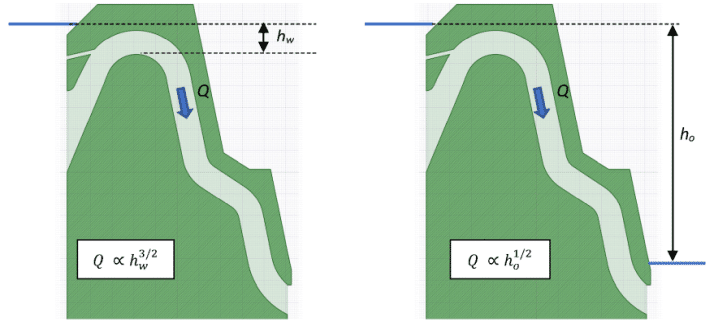
Air-regulated siphon spillways operate under different hydraulic conditions depending on the upstream water level (McBirney 1957). For relatively small heads over the crest of the spillway, the siphon operates like a free weir with atmospheric pressure inside the siphon barrel (i.e. discharge will be proportional to hw3/2). As the head increases, flow within the siphon barrel transitions to pressurized flow; the siphon barrel will be primed with sub-atmospheric pressure. At that stage, discharge through the siphon barrel is like that of an orifice (i.e. discharge will be proportional to ho1/2). The driving head through a primed siphon is equal to the differential head between the upstream water level and the water level just downstream of the siphon exit. Because the effective head on a primed siphon (ho) is, in general, significantly larger than the head over a free siphon (hw), the primed siphon can convey a significantly larger amount of flow when compared to a free siphon with a slight increase in the upstream water level (Ervine 1976). However, this is only true if the siphon actually primes (Tadayon and Ramamurthy, 2013). During floods and emergency events, it is extremely important that a siphon self-primes without human intervention, but this is not always what occurs.
To enhance priming, deflectors are often installed along the floor of siphons to generate a jet directed towards the opposite wall to enclose a confined volume of air. The increased turbulence generated by the jet gradually removes the confined air, dropping the pressure within the barrel.
As the upstream water level drops, the prime within the siphon breaks and flow switches back to atmospheric pressure. As this transition occurs, the discharge decreases significantly, with the head-discharge relation switching from an orifice to a weir.
FLOW-3D Modeling of a Siphon Spillway
Northwest Hydraulic Consultants used FLOW-3D to evaluate the discharge capacity of an existing 3-ft high rectangular siphon spillway. Our civil and environmental customers now use FLOW-3D HYDRO for these types of modeling and analysis. Since the existing siphon experienced issues with self-priming during floods, a hooded air vent at the entrance and a floor deflector within the barrel were added. The first animation below, shows a section model of the siphon with increasing upstream water level.
The first animation was conducted with a fixed upstream water level that was determined from field observation at the existing spillway. The deflection of the flow by the floor deflector results in a confined volume of air within the barrel. Over time, this air is entrained by the flow resulting in the absolute pressure within the barrel to drop from atmospheric (~2,115 lb/ft2) to sub-atmospheric (around 1,500 lb/ft2). As the pressure drops within the barrel, air is removed and replaced by water. The discharge through the siphon increases from less than 1 cfs to more the 16 cfs when the siphon is primed, and the barrel runs full.
The second animation illustrates the siphon prime break action as the upstream water surface elevation decreases. The process of siphon prime break occurs when the difference between the atmospheric ambient pressure and pressure at the crown of the siphon barrel exceeds the differential head required to entrain air into the siphon. Hence, the siphon prime breaks and air replaces fluid within the barrel. As shown in this animation, after the siphon prime break action is complete, inside pressure and discharge through the barrel return to their original weir flow values.
The results of FLOW-3D HYDRO were confirmed by a physical model study conducted at Northwest Hydraulic Consultants’ hydraulics lab.
References
Ervine, D. A., (1976). “The Design and Modelling of Air-Regulated Siphon Spillways.”, Proceedings of the Institution of Civil Engineers, Vol. 61, pp. 383-400.
McBirney, W. B. (1957). “Some Experiments with Emergency Siphon Spillways.”, US Bureau of Reclamation, PAP-97.
Tadayon, R. and Ramamurthy, A. S., (2013). “Discharge Coefficient for Siphon Spillways.”, ASCE Journal of Irrigation and Drainage Engineering, Vol. 139, No. 3, pp. 267-270.
USBR. (1987). “Design of Small Dams.”, 3rd Ed., U.S. Government Printing Office, Washington, DC.

