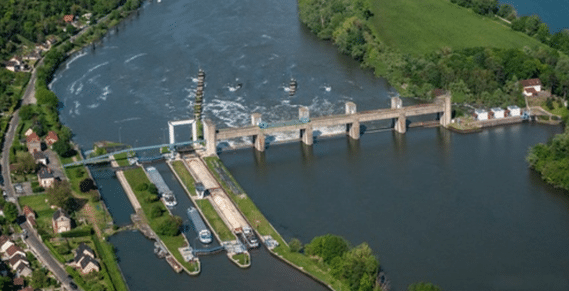
Reconstruction and extension of the Méricourt locks: Study of hydraulic operations
This article was contributed by Gwenaël CHEVALLET, Chloé CHENE, Antoine HALBARDIER, and Franck RANGOGNIO, BRL ingenierie.
With more than 60 years of experience in large scale hydraulic infrastructures, BRL Ingénierie is a leading company in the navigation sector both in France and abroad.
Modeling Premise
The design of a lock and the associated lock management operations are complex problems that are typically addressed using:
- Scaled physical models that can be laborious to implement.
- Issue-specific empirical methods often coupled with calculation approaches.
- 1D transient hydraulic studies to verify compliance with average velocity, water line slopes and locking times criteria.
- 3D steady-state hydraulic models for the filling and emptying of valve elements.
- Charts or simplified calculation approaches for mooring problems.
- Feedback from operators.
The BRL ingénierie teams implemented a methodology to address these modeling needs in a combined way using transient 3D CFD hydraulic analysis with the CFD software FLOW-3D. Our civil and environmental customers now use FLOW-3D HYDRO for these types of modeling and analysis.
Methodology
The renovation and extension project of the Méricourt locks on the Seine aims to rebuild the existing locks, as they present visible structural disorder, particularly through the deformation of the lock walls. The site currently holds two parallel functional locks, one with a 160m capacity lock chamber, and the other with a 185m capacity lock chamber. As part of the scope of the project, the owner (Voies Navigables de France, VNF), aimed to, among other objectives:

- Extend the 160m lock to standardize the capacity of the locks, thus securing the navigation axis. This extension will lead to an increase in the filling and emptying volumes.
- Install floating bollards to replace the existing fixed bollards.
- Replace the downstream valve parts (2 aqueducts replaced by 18 valves).
These changes come with a strong requirement from the owner to maintain locking times close to the current 15min locking time, and at the same time comply with maximum force limits on the bollards, 250 to 300kN per bollard (25 to 30 tons).
The model presented here is for lock no. 1 (L=185m, W=17m) and includes:
- A 3D CAD lock geometry
- A FLOW-3D HYDRO transient 3D hydraulic model capable of simulating all the complexities of the flow (stationary flows, eddies, air entrainment, cavitation, water hammer, etc.)
- Prescribed and coupled moving objects modeling in FLOW-3D HYDRO
- Coupled to the fluid:
- A Grand Rhénan type boat (ECMT class Va, L=110 m, w =11,4 m, capacity 1500 to 3000 tons)
- Coupled to the fluid:

- Floating bollards
- Prescribed motions of upstream aqueduct gates or downstream valves in accordance management instructions.
- A mooring module linking the vessel to the bollards
- A collision module between the boat and the lock walls


Results
Once the boundary conditions were set (forebay and tailbay water levels) and the characteristics of the vessel and the mooring plan were chosen, the implemented model allowed for detailed evaluation of the following conditions:
- Duration of a filling or emptying cycle for given management instructions.
- 3D hydraulic conditions of the flows in the airlock (mainly velocity distribution).
- Forces transmitted in the bollards during a filling or emptying cycle.

Based on simulation results, it was then possible to optimize the filling or emptying management instructions in order to:
- Ensure compliance with the maximum forces in the bollards
- Minimize the duration of the locking times (about 10 to 11 minutes) while respecting the material constraints of the valve components (range of operating speeds of the oil circuit pump in particular).
Conclusion
FLOW-3D HYDRO made it possible to evaluate the design and optimization strategies related to locking (emptying/filling time, hydraulic loads, forces on the boat and forces on floating bollards, etc.) with a single tool. It is in fact a real step forward for the practice. Indeed, this methodology is applicable to all types of locks and all types of vessels.
The results of the modeling carried out so far are particularly satisfactory and are aligned with all order of magnitude calculations using charts, simplified methods or based on the operator’s feedback (emptying/filling laws, flow coefficients of the valves, maximum forces on the bollards, etc.).
Concerning the forces on the bollards (essential dimensioning parameters), the results are obviously tied to the filling schedules, the free length of the mooring lines and their rigidity, as well as to the general mooring plan (number and position of mooring lines), detailed parameters which are all included in the FLOW-3D HYDRO model.


