Microfluidic devices like lab-on-a-chip involve parallel and automated routing, mixing and reacting of a multitude of liquid samples. One way of performing these actions is using thermocapillary actuation. Thermocapillary actuation does not require any external mechanical forces, and therefore is a cleaner and more cost-effective way of transporting fluid samples.
This case study demonstrates the thermocapillary actuation technique of automated routing of liquid droplets in micro-devices. Thermocapillary actuation involves propelling fluid in a certain direction based on the variations of the temperature-dependent surface tension of the fluid. However, due to the inherent wettability of the material surface, some fluid loss takes place during the routing process. Such losses, while the fluid droplet is in motion, are minimized by proper arrangement of hydrophilic and hydrophobic patterned surfaces.
Physics
Thermocapillary stresses induced by spatially-varying surface tension triggers motion in the fluid. This spatial variation is caused because surface tension is higher in the colder regions. Higher surface tension exerts a higher tangential surface force, pulling the fluid together. Therefore, the fluid is pulled from the warmer to the cooler regions. This propelling of the fluid can be explained by the following equation:
$latex v=\frac{h}{{2\mu }}\left| {~\frac{{d\gamma }}{{dT}}} \right|.\left| {\nabla T} \right|$
where $latex v$ is the velocity of the propelled fluid, $latex h$ is the height of the thin fluid film, and $latex \mu $ is the fluid viscosity. The variation of surface tension $latex \gamma $ with temperature $latex T$ is given by $latex \frac{{d\gamma }}{{dT}}$. Thermal gradient $latex \nabla T$ that induces change in $latex \gamma $, propels the fluid with a velocity $latex v$.
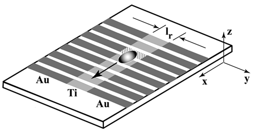
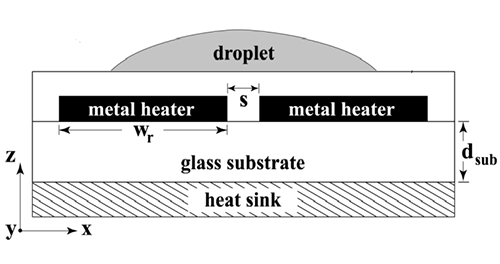
Spatial variation in surface temperature, in combination with hydrophilic surface in the center and a surrounding hydrophobic surface, provides an effective microfluidic system for fluid routing with no lateral fluid loss. A fully wetting surface causes more fluid loss, therefore it is ideal to keep a partially wetting surface. Spatial variation in surface temperature can be attained by using programmable microheater arrays as shown below.

FLOW-3D Setup
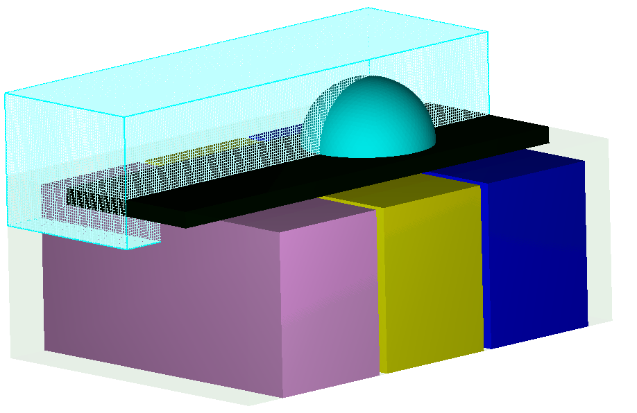
The main simulation steps of geometry creation, meshing, boundary condition definitions and initial conditions were very easy to set up for this case study. Particularly, the use of structured meshes and inbuilt primitive geometry shapes in FLOW-3D makes meshing and geometry creation simple.
Multiple physics – heat transfer, surface tension and viscosity – are at play, highlighting the comprehensive multiphysics modeling capabilities of FLOW-3D. The physical properties of water were used in the simulation, but any fluid material for which physical properties are identifiable can be modeled.
Results
The animation below shows a comparison between a fully-wetted and a partially-wetted surface. As expected, the fully-wetted surface makes the droplet flatter (and more spread out) than in the partially-wetted surface. As the heaters are activated, one at a time, the droplet is propelled towards the colder region. It can be seen that the fully-wetting surface loses more fluid volume by the end of the simulation as more fluid is left behind. Therefore, using partially-wetting surface is a better option that reduces fluid loss. In both cases, the droplet is forced to stay in the middle because of the central hydrophilic strip surrounded by a hydrophobic surface.
FLOW-3D’s powerful free surface and surface tension models can be readily appreciated in the evolution of the droplet surface over time as the microheaters are activated in programmable manner. The droplet is almost instantly propelled forward each time a heater is activated. This propelling can be seen at around t=0 and t=0.02 seconds. Also, notice the dynamically changing free surface shape and contact angle of the fluid droplet every time it is propelled.
There can be an array of tens and hundreds of heaters to transport fluid to longer distances, although still within the micro scales. The simulation below shows a case with four heaters. All the settings are similar to the previous 45 degree contact angle case except for an additional heater, showing greater displacement of the fluid droplet.
As the last in a series of blogs related to microfluidics and multi-physics processes, this case study highlights once again the ability to use FLOW-3D to simulate such multi-physics, micro-scale processes with good results.
Reference
Anton A. Darhuber, Joseph P. Valentino, Sandra M. Trian, Sigurd Wagner, Thermocapillary Actuation of Droplets on Chemically Patterned Surfaces by Programmable Microheater Arrays, Journal of Microelectrochemical systems, Vol. 12, No. 6, December 2003
Learn more about the power and versatility of modeling microfluidic applications with FLOW-3D >


