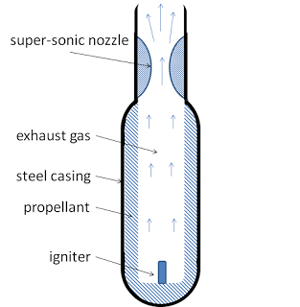
Solid fuel combustion is a traditional method of extracting energy from solid objects. However, an important relatively new application of solid fuel combustion is in rocket propulsion. The development of the Combustible Objects model in FLOW-3D was motivated by solid propellant combustion in rockets. The model describes the conversion of solid rocket propellant to gas with a heat source, mimicking the combustion process in solid-fuel rockets.
The Physics Behind the Model
The burning of the propellant in the combustion chamber results in increased temperature and pressure of the surrounding gas. In addition, as propellant is burned, the flow domain increases. It is of interest to predict these changes in the flow because the dynamics (e.g., trajectory and velocity) of the rocket depends on them. To account for the changes in the size of the flow domain, a variant of the General Moving Object (GMO) model has been developed. In the augmented model, the geometry component representing the solid propellant is designated as a GMO component of a special type: instead of moving, it changes shape and size. Such deformation of a combustible part can be seen in the simulation at the end of this article. If the elastic stresses within the solid propellant need to be modeled, the Fluid-Structure Interaction model will work with this new development.
The mass source of the combustion gas is assumed to be of stagnation type, i.e., the initial velocity of the exhaust gas is zero. As a result, no additional source term is present in the momentum equations. The combustion rate is defined by the equation below. dm/dt is the combustion rate or, simply, the rate of change of mass of the solid propellant, P is the pressure of the combusting gas, and a and b are empirical parameters.
How to Set Up the Model
The model requires that the compressible flow model is activated. The solid propellant is defined as a special type of geometry component – combusting and the reaction parameters (a and b) need to be defined. Default values for multiplier and power coefficients are given, but these values can be changed by the user. The default values for multiplier and power coefficients are 1e-05 and 0.5, respectively. These values can be changed by the user.
An Example Simulation with Results
This simulation is of a solid propellant combusting inside a rocket. The design used for the rocket part along with the real part is shown in Figure 1. A cylindrical mesh was used because of the cylindrical geometry of the setup.
Evolution of gas pressure (evolution with time is shown in Simulation 1), velocity, and combustion gas mass fraction is typically what a user will likely study. Courant number is also shown in the results (Figure 2), which is a ratio of the distance traveled by fluid in one time-step to the mesh cell size.
Courant Number
Higher values of Courant number indicate that the time-step size may be too big to accurately capture the local flow parameters. In Figure 4, the Courant number stays low inside the ignition chamber but increases as the flow transitions from the chamber to the nozzle. Since the main purpose of studying this case was to simulate the behavior of combustible object, as far as the ignition chamber goes, the Courant number there is low, ensuring an accurate solution. This may not be the case in the nozzle, but the user can reduce the time step to run the simulation at a lower Courant number, if required.
Explicit vs. Implicit
By now you might have thought about the numerical complexities involved in this simulation. The overall time-step size is limited by the advection velocity in the nozzle, which may lead to large computation times. An implicit advection scheme could be used to speed up the calculations. However, the time step-size must be carefully controlled to minimize the errors associated with the implicit scheme.
Pathlines and Circulation
Pathlines are excellent mathematical functions and visualization tools to understand the history of a fluid particle in the computational domain. A strong visualization tool like FlowSight calculates the pathlines depending on user’s requirements in terms of length, number, etc. Figure 3 shows the combustible part from the bottom (longitudinal direction) in the top-left viewport. The pathlines are calculated and visualized in the main viewport (the figure in the center). At one glance, it can be seen that a significant amount of local circulation is happening, along with a global circulation at the periphery. Such physics may be important to understand while programming the trajectory of a rocket.


