Interaction Between Waves and Breakwaters
Modeling Rubble Mound Breakwaters
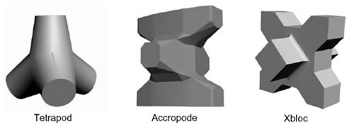
The following examples describe cases where rubble mound breakwaters are modeled on the basis of their real geometry, taking into account the hydrodynamic interactions with the wave motion.The work takes into consideration a schematic representation of a natural stone mound, reproduced as a set of spheres, and was further developed to consider commonly-used artificial blocks such as the cube, the modified cube, the antifer, the tetrapod, the accropode, the accropode II, the coreloc, the xbloc,and the xbloc base (Fig. 1).
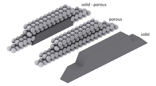
Breakwaters, both submerged and emerged, were sized by making use of standard empirical formulas as available in the literature and numerically constructed by overlapping individual blocks following real geometric patterns, modelling the structure as in the full size construction and in the physical modelling (Fig. 2).
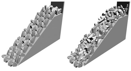
In order to validate the quality of the proposed procedure, three different geometries were considered for the submerged breakwater: solid, porous, solid-porous (Fig. 2a), while for the emerged breakwater, two different geometries were used, according to the shape of the elements: regular and random (Fig. 2b – 2c).
Once the breakwaters were defined, the geometric configuration was imported into FLOW-3D and tested for the study of wave propagation in order to assess the hydrodynamic interactions. The simulations were carried out by integrating the Navier-Stokes equations in three dimensions, using the RNG turbulence model and a computational grid with a fine mesh nested inside a larger coarse grid.
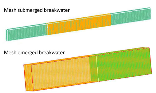
For the submerged barrier (calculation domain: 90×1.9×6.5m), the containing mesh block consisted of 46,200 elements of equal size (0.30×0.27×0.30m), while the nested block was located at the breakwater with 2,353,412 elements of equal size (0.061×0.055×0.061m).
The same criterion was adopted for the emerged breakwater. The containing mesh block consisted of 150,000 elements (0.50×0.20×0.30m) and the nested block was created with 2,025,000 elements (0.10×0.10×0.10m) (Fig. 3).
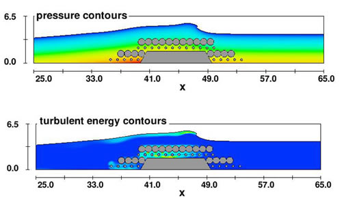
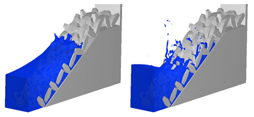
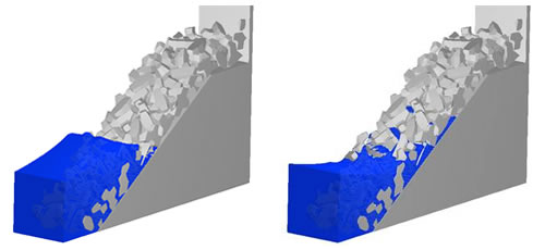
Some of the results are summarized in the following images. In Fig. 4, the evolution of pressure and turbulent energy along a two-dimensional section of the 3D domain is represented. In Fig. 5, the three-dimensional configurations of the free surface, caught in different moments of time, are shown.
The variation of the hydrodynamic quantities along the flow paths and along the contour of the individual solid elements of the primary armour are easily detectable. This is most visible in three-dimensional reconstruction of the free surface (Fig. 5) where the effects of wave action on the breakwater are represented with greater details.
Conclusions
A method utilizing Navier-Stokes-based numerical simulation to provide an accurate representation of the interactions between a maritime structure, either submerged or emerged, and fluid motion has been demonstrated. Simulations were carried out by making use of an advanced computational fluid dynamic software system (FLOW-3D), involving RANS for turbulence simulation and VOF for free surface computation.
The results show that the procedure provides a detailed picture of the fluid motion within the paths among the blocks, thereby offering a more accurate simulation than the conventional seeping flow methods. In principle, there are no limitations on the possibilities of simulating the structure, both submerged and emerged, in all its relevant parts (filter, core and toe).
Further studies will be aimed at assessing the stability of individual blocks through the use of the Moving Object model in FLOW-3D.
