Design optimization is a mathematical technique that can be used, together with computational fluid dynamics, to identify the best design to achieve one or more desired objectives, while taking into account a spectrum of design parameters and constraints. Optimization has become more and more popular in recent years as quality requirements increase and computational resources become faster and more-powerful, allowing for iterative runs.
An earlier blog on design optimization showcased a case study to improve the mixing efficiency of a microfluidics device. In this blog, I will present a proof of concept from the metal casting industry – optimization of gravity casting filling system – using FLOW-3D CAST and CAESES®, an optimization tool developed by Friendship Systems GmbH, in Potsdam, Germany.
In the presented case (and in metal casting in general), our objective is to minimize defects given certain limitations on the geometry and process parameters. Additionally, by using CAESES, we will greatly reduce the amount of post-processing and evaluation because we will not be running all the simulations and then manually comparing the results.
Optimization Study
Below is the gating system and casting part that will be the subject of the optimization study. At first glance, it may appear to be a poor design because the gates are too high allowing the metal to drop into the casting. The turbulence generated as the metal falls into the casting will entrain air and likely result in a casting which fails to meet quality specifications. This is because entrained air, also known as gas porosity, can reduce the soundness or structural integrity of the casting and must be minimized in critical areas. But the design reflects the geometry limitations mentioned above, and represents one of the principal constraints we had to deal with.
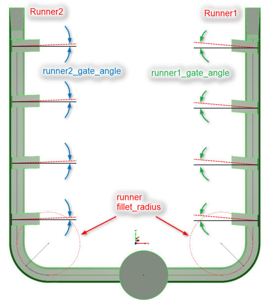
To mitigate this, we will have the optimization algorithm adjust the size and angles of the gates, the sprue size, the cup size, and the runner fillet in a way that minimizes the volume of entrained air in the casting, which will improve the quality of the resulting part. A taper runner was also added to the end of the runner system to help capture defects. In addition to minimizing the volume of entrained air within the casting, we’ll observe the temperature profile, which can indicate both surface defects and early solidification, and constrain the system so that the velocity at the gates does not exceed 0.5 m/s which is widely accepted as the maximum velocity of metal (Campbell, 1997;2003). The table below lists the parameters changed and the range that they were changed. There were five geometry variables run within a range with an upper value and a lower value.
| DESIGN VARIABLE | LOWER | UPPER | |
| 1 | runner1 gate angle | 0 | 20 |
| 2 | runner2 gate angle | 0 | 20 |
| 3 | sprue area k length | 1.2 | 1.6 |
| 4 | cup scale | 1.2 | 1.7 |
| 5 | runner fillet radius | 5 | 15 |
The figures below show the adjustable parameters in the runner geometry.
Optimized Casting
Overall, the statistics alone may not give enough information to determine whether the design has been improved since the location of the defects is just as important as the volume of entrained air but this effect was not included in this simplified proof of concept. However, it would be relatively easy to adjust the optimization criterion to include this effect by adding sampling volumes in critical locations and then minimizing the volume of entrained air contained by all of the sampling volumes.
Here we see a sample of the statistical outputs.
History probes were used to ensure that the velocity at the gates were not larger than 0.5 m/s. The optimized runner system is shown below.
Optimized Geometry Parameters
| Design Variable | Optimized Values | |
| 1 | runner1 gate angle | 1 |
| 2 | runner2 gate angle | 0 |
| 3 | sprue area k length | 1.3 |
| 4 | cup scale | 1.6375 |
| 5 | runner fillet radius | 14.5703 |
Optimized Runner System

Now, let’s compare the original results of the air entrainment and temperature to view the locations and quantity of defects. The final results of entrained air compared with the original are shown below.
In the image from the post-processed results of the optimized case, the volume of air entrainment has been removed along the sides of the casting and more of the entrained air has been placed in the risers. Ideally the gas porosity should end up in the risers. The graph demonstrates the reduction in overall volume of entrained air in the casting achieved by the optimization of the runner system. In total, the volume reduction was 13%.
The figure below shows the comparison of temperature gradients between the best and original casting parts.
The temperature profiles are similar in the figures above. The heat has been removed in one region but has been added more in other regions. Surface defects can be determined based on cold regions and hot regions indicate possible shrinkage porosity depending on the feeding.
Conclusion
FLOW-3D CAST and CAESES can be used to improve the quality of a metal casting by setting an objective (reducing defects) and achieving it through geometry (e.g., improving the runner system design) and process parameter optimization. For this study, the objective was to minimize air entrainment while ensuring a stable temperature profile and gate velocities of less than 0.5 m/s. The volume of entrained air was reduced and moved to other locations while the temperature gradient changed in some locations. Similar studies can be used for several other defects (surface defect, shrink, spray time, etc.) and types of simulations (thermal die cycle, solidification, and stress on die or casting part) to improve the casting quality.


