FLOW-3D allows users to import solids in STL (StereoLithography) format to represent complex geometries, regardless of the application – micro fluids, metal casting, water and environmental, aerospace, etc. While for many industries, the STL format is a very natural and common way of representing and sharing 3D objects, in the water and environmental industries there is a preference towards surface-driven representations of the environment. After all, the earth’s terrain does look like a surface for most practical purposes.
Raster Data Interface
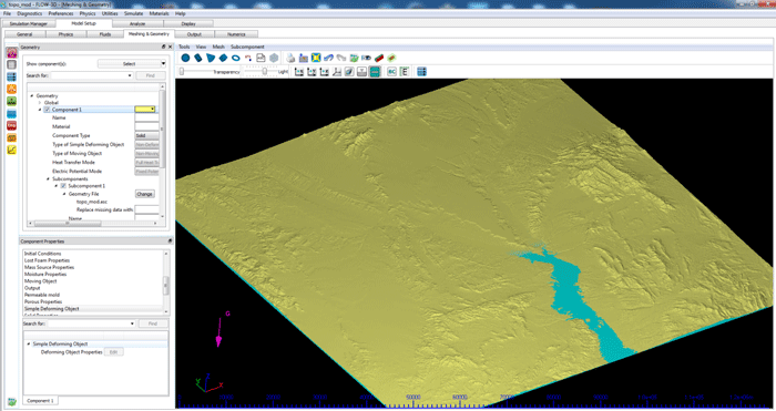
In the upcoming release of FLOW-3D v11.1, we have adopted an industry norm for terrain import: the file format known as the ESRI ASCII raster format. All GIS software packages are able to export in this format. Such *.asc terrain files will now be able to be imported directly (Figure 1) into the FLOW-3D user interface.
Subcomponent Specific Surface Roughness
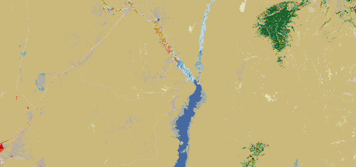
Alongside terrain import, a critical modeling variable in modeling flood wave propagation, flooding area, etc., is surface roughness. In particular, the user needs to model local, spatially-varying surface roughness. In FLOW-3D v11.1, users will be able to import surface roughness coefficients in the same ASCII raster format.
More specifically, the user actually imports a raster file of the land coverage index and provides a simple text file palette conversion table. This table converts the type of land coverage (sand, vegetation, built-urban, etc.) defined in the raster file to surface roughness values that are required by the FLOW-3D solver. This gives the user a very effective way to fine tune the surface roughness coefficients without having to regenerate the entire raster file by simply altering the palette conversion table. The ASCII raster format was chosen because it remains simple, yet lets the user easily control the surface coefficients that are mapped over the domain following the land coverage types.
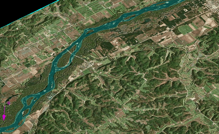
In the same framework of modeling complex flood events, functionality to overlay actual pictures of the environment, such as river banks, built structures, and developed housing has been added. FLOW-3D v11.1 allows users to directly texture their terrain with corresponding imagery, typically obtained from satellite imagery.
This operation can be conducted in two stages in FLOW-3D. The first stage is during model setup (Figures 2 and 3), so that the user can see the context of the model he or she is building, making it easier to be sure the simulation is properly set up. The second stage is during post-processing in FlowSight. This is where the overlay of the flooding event and the terrain imagery is used to reveal the extent of the flood zones and the interaction of the flood wave with the environment.
Example Simulations and Conclusion
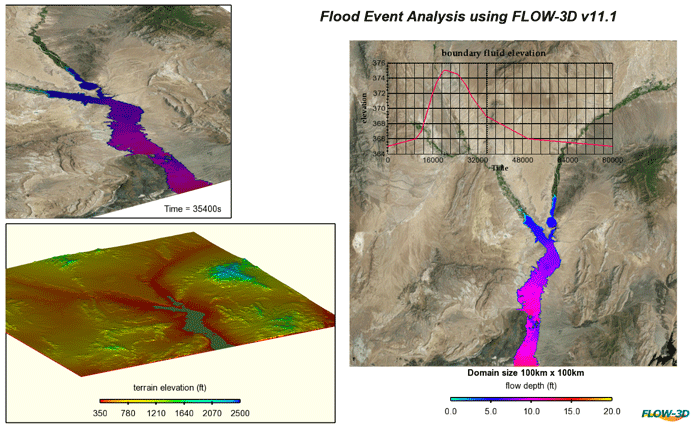
Figure 4 shows the results from flood routing of the streams in two different terrains. Upstream elevations have been plotted for the example cases. Note that the analysis has been done on a terrain overlaid with surface roughness data. The ability to import raster data and overlay it with surface roughness provides the user a single platform, i.e., FLOW-3D, to conduct the water and environmental studies on the terrain. Typical flood wave propagation through a stream can be seen in the simulation below.
