Thermal die cycling is a standard process die casting facilities use to get their die up to temperature for full production. Think about showing up to work in the morning, mid-winter: your machines are cold! Typically someone will fire the die to get the machines warmed up and then go through a series of “dry shots” where the parts are considered sub-par quality or have a high potential for defects. After a handful of cycles (around 10), the die is hot and has a consistent temperature distribution throughout, ensuring consistent results. The series of dry shots informs you about your cooling channels’ performance and whether you need to re-locate or up the flow rates, before building any tooling. This process can be effectively simulated in FLOW-3D CAST v4.1, saving valuable time and decreasing costs even more.
The Physics Behind the Model
The Thermal Die Cycling model in FLOW-3D CAST v4.1 provides accurate calculations for the following physics:
- Assessing thermal distribution of die/tooling
- Heat removal rate of the cooling channels and their locations
- Thermal analysis of the entire casting process for tooling design to assess large volume (or small volume for prototyping) thermal development and a steady operating state
- Parting line cooling during the die spraying and cleaning stages
- Cooling of the cover and ejector at different rates during a period of high thermal gradients during the ejection stage
Apart from the physics there are stages in a thermal die cycling process that can affect the results of the simulation, e.g., leaving the part in the die during the ejection stage changes the nature of the heat transfer for all components involved. Similarly, along with the cooling lines the parting lines should also be modeled. The Thermal Die Cycling model considers all such scenarios to accurately predict the actual process.
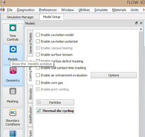
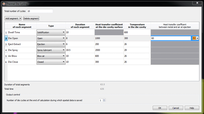
The Thermal Die Cycling model can be accessed in the Casting Models tab of the Models window. On clicking Thermal Die Cycling (Figure 1), a Thermal Die Cycling window will pop up (Figure 2).
How do I Use the Model?
The Thermal Die Cycling model is easy and intuitive to use, however, there are certain requirements for various design stages to ensure that the model gives accurate results that I will talk about in the following paragraphs.
Requirements for different stages
You can define each step of your own process but the first step must always be “Solidification.” We give you options to define different cooling heat transfer coefficients at all stages during each cycle. The ejection stage allows you to define different values for both the cover and ejector for accurately simulating the differential cooling rates of the cover and the ejector. The difference in cooling rate arises because while the part remains in one side of the die (typically the cover), there will be a different thermal profile between the ejector/cover sides.
For the rest of the stages, and in between these stages, you can rearrange and re-order as you need. For example, if you were to air dry before and after your lubrication stage, you may in fact remove too much heat so you might test different arrangements of your process. Another problem might be that you are not removing enough heat during the spraying/cleaning stages. This aspect of the analysis is extremely easy to change and can be done in columns 3 thru 5 (Figure 2). Depending on how long you are spraying the die, or what you are spraying with, your heat removal can change. Take room temperature oil for 10 seconds versus cooled water for 1 second, both will react very differently with your die surface temperatures and thus the total heat removed will also differ. We allow you to quickly assess these differences before you have to manufacture any tooling, a huge cost savings and improvement of your bottom line. Now, if these practices do not succeed in maintaining your thermal profile, you know that you will need to re-assess the locations of your cooling channels in order to get your desired outcomes and once again, this is a huge cost savings for your company. Manufacturing a set of die tooling only to find that your cooling lines are inadequately placed is a setback that can be easily avoided using this model and can get your parts to market as fast as possible.
Accuracy
Finally, this model essentially “turns off” all fluid dynamics calculations and the physics involved are strictly heat transfer based (conduction only). This allows for extremely fast simulation results and can be easily worked into a facility’s workflow. The fully-developed heat distribution throughout your die as your initial condition for your consequent filling and solidification simulations will allow for an accurate assessment of your temperature-related defects. It also helps to identify early solidification issues before you send the designs off to be manufactured, avoiding potentially catastrophic flaws.
Sample Simulations
Two sample simulations of a heat exchanger for a consumer product are shown below. Simulation 1 models the die spray stage and evolution of the temperature profile on the ‘surfaces’ of the two die components, the ejector and the cover. The surfaces where the die components come together during a shot are referred to as the ‘parting lines,’ where a majority of the heat removal will take place. This stage also acts as a cleaning stage in reality, but since we do not model leftover residues, we do not take this into account.


