
Liquid Metal 3D Printing
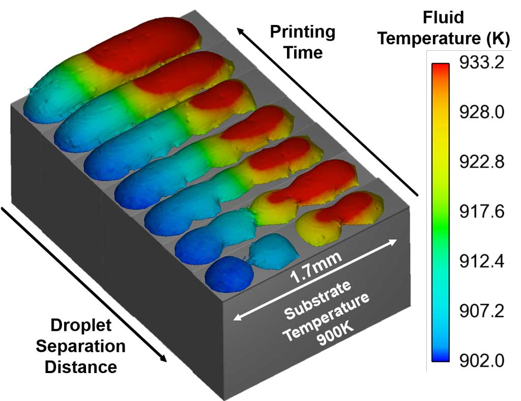
In this article about the simulation of liquid metal 3D printing, we will discuss a novel approach to additive manufacturing of 3D metal structures.
Non-Newtonian Ink Additive Manufacturing
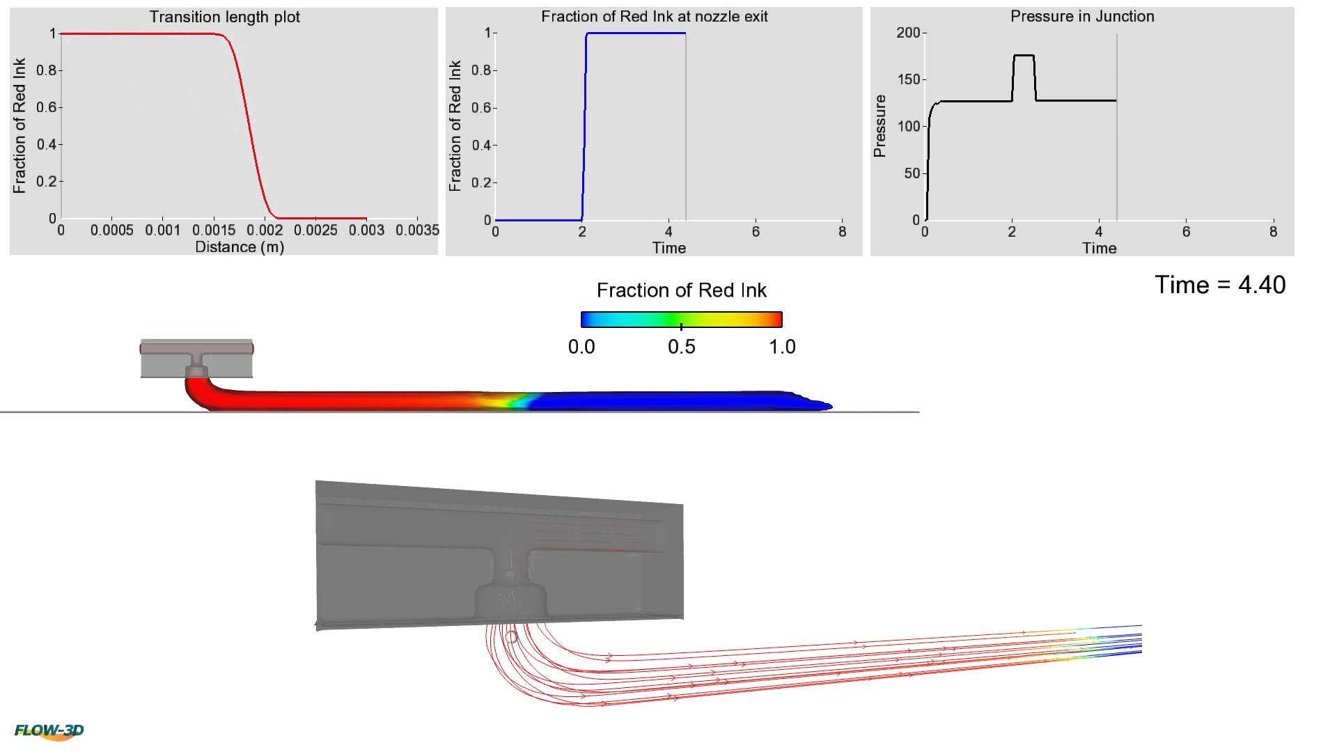
Non-Newtonian ink printing is the future of additive manufacturing. It does not require added heat, instead relying on a pump to eject any number of materials with thick consistencies onto a build platform. However, like any other 3D printing method there is an issue when multiple inks are used for the same product.
Laser Powder Bed Case Study
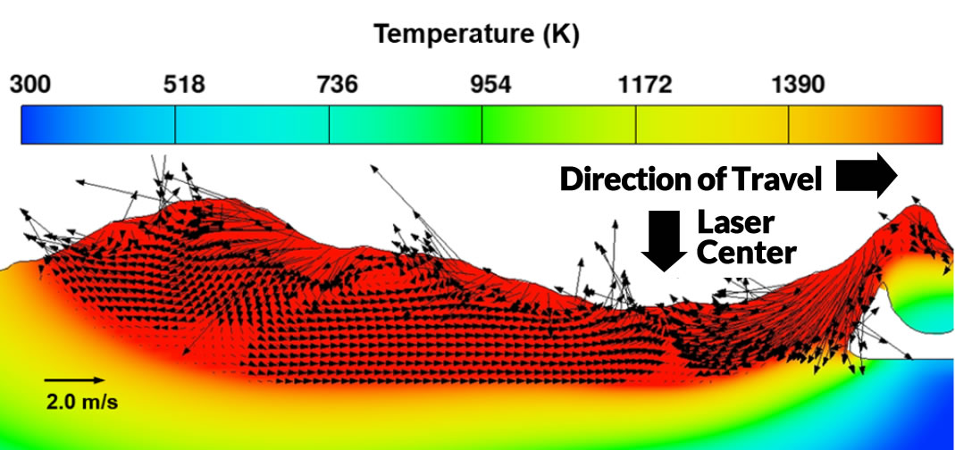
Laser-powder bed fusion additive manufacturing involves complex physical processes. Particularly, the absorbed laser beam energy melts the particles and forms a molten pool where a strong fluid flow occurs driven primarily by surface tension gradient.
