FAVOR™ vs. Body-Fitted Coordinates
Table of Contents
The simplicity of the fractional area/volume FAVOR™ method for modeling complex geometric regions is very attractive. But, does its accuracy compete with deformed grids like finite-element or body-fitted coordinate methods? A comparison between these methods shows that there are only small differences between the inherent capabilities of the two approaches.
In the absence of solid boundaries there is little fundamental difference between grids of differently shaped control volumes. Some methods require users to store more information (e.g., node locations and various geometric factors) and some exhibit differing levels of accuracy depending on the amount of element distortion. In all cases, however, the underlying idea is a discrete approximation in which fluid forces and fluxes are computed for each element in the grid.
It is the issue of obstacle boundaries that is most often raised as an advantage of deformable grids because they can be constructed to fit the geometry. Two consequences come with this flexibility. One consequence is that these grids must be unstructured for general use. This is because structured grids can only undergo limited distortion before elements are turned inside out. The other consequence is that the distortion of an element makes it more difficult to construct accurate numerical approximations.
Structured FAVOR™ Grids vs. Unstructured Grids
The FAVOR™ concept can be used in connection with any type of grid including grids consisting of rectangular or distorted elements and whether the grid is structured or unstructured. Structured grids are best because they are easy to generate and the indices for neighboring elements are known. Rectangular grid elements make it easy to compute the fractional areas and volumes of elements used by the FAVOR™ method.
The ease with which structured, rectangular grids can be generated makes this an obvious choice for the FAVOR™ method. However, the specification of open and closed grid regions implicit in the FAVOR™ method introduces a type of unstructured computing environment, because only those elements having a finite amount of open volume are actually computed. This results in a computation that is analogous to an unstructured grid computation.
The analogy with a true unstructured grid is not perfect. For example, the FAVOR™ method requires storage for all elements whether they are blocked or not, while unstructured grids require storage of neighbor lists. Storing all elements is the price paid for automatically knowing which elements are neighbors. Of course, if heat conduction is to be computed in the solid regions surrounding a fluid, then blocked elements must be kept anyway.
One disadvantage associated with rectangular, structured grids is that they cannot be distorted to increase resolution in a localized region. Grid lines can be constructed closer together in a particular region for increased resolution, but these grid lines then extend across the entire grid. As a result, the number of elements in a grid may become large. Offsetting this disadvantage is the simplicity of grid generation. There is also the possibility of introducing multiple grid blocks joined at their boundaries to provide increased local resolution without a large increase in the number of grid cells.
The FAVOR™ method is seen to have properties analogous to unstructured grids but without the overhead associated with the construction of unstructured body-fitted or finite-element grids. Since grid generation often requires a major investment of time and effort, the elimination of this task makes FAVOR™ a very desirable alternative.
FAVOR™ Elements vs. Body-Fitted Coordinate Elements
A second issue with deformed grids is that their deformation can be used to fit a bounding solid surface. This is accomplished by moving the nodes of elements closest to the surface onto the surface. In contrast, in the FAVOR™ method a surface is allowed to cut through an element and its location is recorded not by moving the edges of the element but in terms of the fractional face areas and fractional volume of the element that are not covered by the solid.
What we wish to show is that this fractional area/volume technique for defining solid boundaries has the same consequences for numerical approximation as does a deformed (i.e., body-fitted coordinates) grid technique.
The most important point to recognize about the FAVOR™ method is that approximations of fluid-dynamic quantities are restricted to the open regions of elements. This restriction introduces fractional areas and volumes of elements as factors directly into the discrete approximations. For example, the flux of a quantity from one element to another has the fractional area of the fluxing boundary that is open to flow as a multiplier.
In this way FAVOR™ and body-fitted coordinates both compute fluxes across the faces of elements that employ the same areas. In FAVOR™ the areas are stored as fractions of the original element face areas. In a BFC method the areas are computed from the coordinates of the nodes defining the faces, and often times they are also stored so they don’t have to be recomputed.
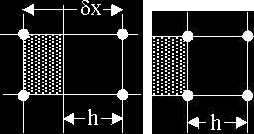
When constructing difference approximations in a grid of non-uniform elements it is necessary to know the effective element widths in different directions. A simple example is given in Fig. 1, which shows an element with a solid boundary. In this case the solid boundary is parallel with the vertical sides of the element. For a deformed element, Fig. 1b, the width of the cell would be h and this width would be used for computing differences in the horizontal direction.
In FAVOR™ the width of the open portion of the cell is equal to the product of the open volume fraction and the original cell width. It is this product that is used in FAVOR™ for difference approximations in the horizontal direction and it is the same as the width of the deformed cell, h.
When differences are computed in a vertical direction, for example, across the top of the element (i.e., parallel to the solid boundary in Fig. 1) the FAVOR™ method approximation involves a ratio of the fractional area at the top divided by the fractional volume. This ratio has a value of unity because the solid boundary blocks the same fraction of area horizontally as it does volume, which again makes the approximation similar to that of a BFC cell. Thus, there is no difference between the effective cell widths used in making difference approximations in FAVOR™ and body-fitted coordinate cells.
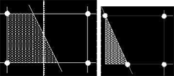
If the solid surface is slanted as shown in Fig. 2, then the top and bottom face areas are different but are still known quantities in either case. Further, the average horizontal width of the open portion of the cell (h) is still the same because the volume fraction does not change when the solid surface is rotated about a midpoint within the cell (see dashed line). Here again there is little to distinguish between a FAVOR™ and a body-fitted coordinate cell.
It is well known that body-fitted coordinate grids can be difficult to construct, and there has been effort devoted to the development of automatic grid generators. It is also well known that even with the best of grid generators it still takes a significant amount of time to establish a workable well-behaved grid.
The simple rectangular construction of FAVOR™ grids makes them extremely easy to generate. Fractional areas and fractional volumes must be computed to define obstacles placed within a grid, but theses computations are well defined and easy to automate using simple algorithms.
Numerical accuracy is not sacrificed when selecting FAVOR™ over a body-fitted coordinate gridding method. The two approaches simply represent different ways to approximate bounding surfaces.
Finally, the numerical advantages inherent in the structured, smoothly varying, strictly orthogonal grids used by the FAVOR™ method should not be overlooked. These advantages, as well as the ability to automatically represent porous media (i.e., another example of a fractional area/volume region) are additional reasons why the FAVOR™ method was selected as the basis of FLOW-3D.


