What’s New – FLOW-3D 2022R1
The new 2022R1 versioning of FLOW-3D products reflects Flow Science’s adoption of a synchronized release naming convention for FLOW-3D, FLOW-3D CAST and FLOW-3D HYDRO. 2022R1 represents the transition to a unified code base for FLOW-3D products. This important evolution will allow users access to the latest developments as soon as they are ready, at a more frequent product release pace.
The 2022R1 release features an extension to the FAVOR™ method called the detailed cutcell representation, the introduction of simulation templates with themed solver defaults, moving droplet/bubble sources, a new axial pump model, extensions to Active Simulation Control capabilities, tabular properties that allow users to specify complex property dependencies based on two independent variables, and additional numerics features such as a VOF-to-particle development to improve mass conservation for fluid regions subject to breakup. Streamlined GUI improvements include redesigned physics dialogs, a new initial conditions widget, and redesigned output and geometry widgets for easier, faster and error-free simulation setup.
Detailed Cutcell Representation – An Extension to FAVOR™
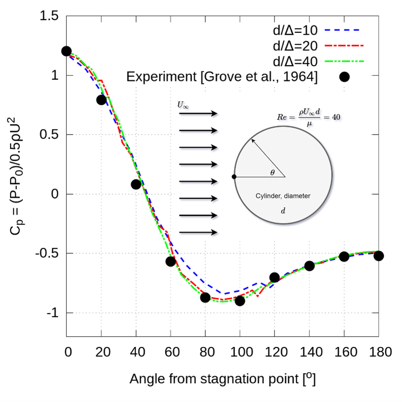
The FAVOR™ method represents solid geometry using area and volume fractions on a regular, Cartesian grid. It enables FLOW-3D to efficiently simulate flow through and around complex geometry without resorting to unstructured body-fitted meshes. For all its considerable computational benefits, one challenge for the FAVOR™ method is that the calculation of wall shear stresses along solid surfaces can sometimes be noisy. An extension to FAVOR™, called detailed cutcell representation, greatly improves the calculation of wall shear stresses, resulting in significant improvements in the solution near solid surfaces.
Learn more about the advanced numerics as well as validations of the detailed cutcell representation.
Tabular Properties
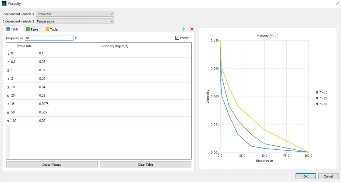
Material properties such as viscosity and surface tension can be dependent on flow conditions such as temperature, density, strain rate, or user-defined scalar quantities representing things like a contaminant concentration. Fitting these properties to functional forms can require complex curve-fitting, especially when the properties are dependent on more than one independent variable. The new tabular properties feature in FLOW-3D allows users to define fluid properties in table form with up to two independent variables. For example, surface tension can be tabulated from experimental data to describe complex, non-linear dependencies on contaminant concentration and temperature, or viscosity can be tabulated from experimental data to represent a dependency on strain rate and temperature. Users can input a single variable or two variable dependency in the tabular properties dialog.
Viscosity is defined as a function of both solid content (density) and strain rate. In this example a dense fluid region slides down into a quiescent pool which at time zero is layered with a dense settled fluid region and clear water above.
Expanded Active Simulation Control
Active Simulation Control (ASC) is very useful for controlling simulations based on flow information at probes. In this release, ASC has been expanded to allow additional controls based on flow information from general history data, flux surfaces, and sampling volumes.
One of the advantages of flux surfaces and sampling volumes over point probes is that they can provide information averaged over a surface or a volume rather than point-based. In some situations, surface-based and volume-based information can be more representative of the behavior of interest in simulations.
With this new capability, users can:
- Terminate a simulation when the temperature in a control volume exceeds or falls below a critical value.
- Control the filling rate from a nozzle based on the turbulent energy in a sampling volume.
- Control the output frequency based the average velocity on flux planes.
- Terminate a simulation when fill fraction in a sampling volume reaches the value specified by the user.
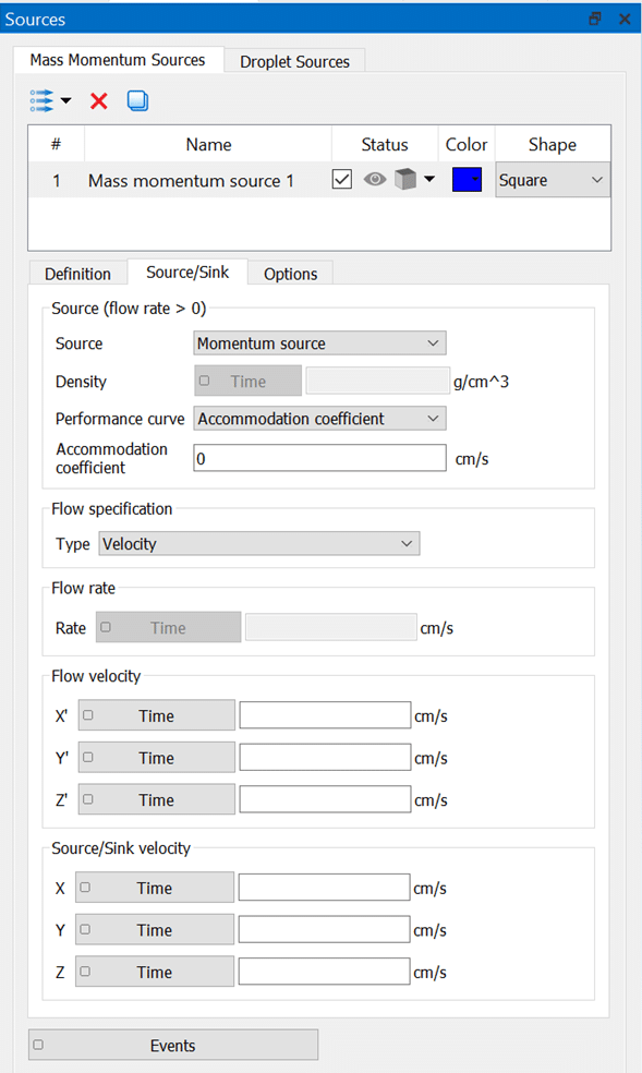
In this example, a pump (dark grey rectangle) in a cryogenic tank feed pipe pulls liquid oxygen from a propellant tank at a constant flow rate. As the liquid oxygen drains, a mass/momentum source (grey bar at top) is triggered by Active Simulation Control when the pressure in the ullage drops below a specified value. Pressurization is turned off when the ullage pressure rises above a specified value.
VOF to Particles
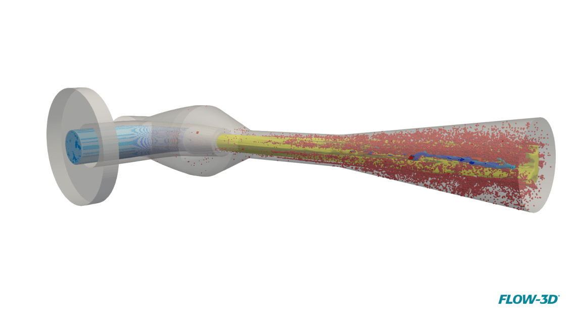
The accuracy and robustness of the sharp-interface tracking VOF methods in FLOW-3D have been enhanced by combing them with fluid particles. The new particle species, called VOF particles, are used in place of the VOF function to track small fluid ligaments and droplets in the computational domain, achieving better conservation of fluid volume and momentum. Higher time steps size can also be expected in gravity-controlled processes. The VOF fluid is automatically converted to VOF particles at certain times and locations when certain conditions are met. The particle motion is then calculated using the Lagrangian particle model and the particles are converted back to the VOF representation upon reentering the fluid.
Axial Pump Model
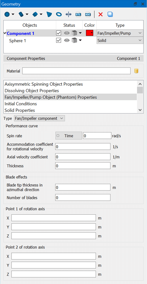
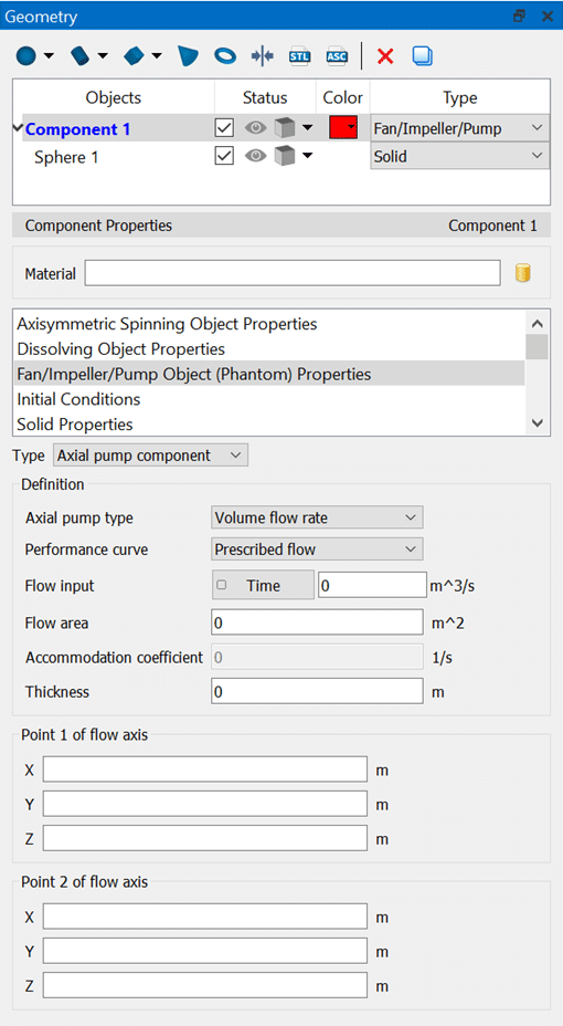
FLOW-3D’s new axial pump model allows users to mimic the net effect of an axial pump in their simulations. There are two options with respect to the pump behavior. The first option is to prescribe either a volumetric flow rate or a flow velocity through the pump so that the fluid is moved at the specified rate. This option is appropriate when an operating flow rate is provided for the pump. The second option provides a more complete definition of the pump operation based on a pump performance curve. In this case, the user can define a linear approximation of the pump’s performance curve so that the flow rate through the pump will depend on the pressure drop across the pump. In this configuration, the typical behavior of a pump is represented, whereby the flow will slow down and eventually stall as a reverse dynamic head builds up and pushes back against the pump operation.
Droplet/Bubble Source Model
Since it was first developed, FLOW-3D has been used to model droplets being ejected from nozzles and other orifice shapes to simulate the resulting fluid shapes evolving under the actions of surface tension. However, there are occasions when simulating the shape of the droplet as it leaves a nozzle is unnecessary, as only the impact of the droplet on a substrate is of interest. Additionally, modeling the transport of a bubble in fluid may be of interest, but not the initiation of the bubble. The new droplet/bubble source model is helpful for cases like these.
The new droplet/bubble source model allows either spherical droplets or bubbles to be emitted at defined intervals from a point source. This source can be either stationary or its motion can be defined in a tabular fashion. The initial velocity of the droplet or bubble can also be defined in three dimensions. All physical models are compatible with this model so that typical applications such as porous media flow, evaporation/solidification, and surface tension can be simulated.
In this example, a droplet source moves in a circular pattern while ejecting droplets downward at a velocity of 10 m/s into a porous medium to create a ring-shaped design.
Simulation Templates
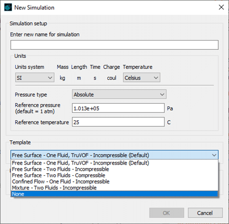
New simulation templates pre-load important parameters based on a given modeling framework, such as one fluid incompressible flow with a free surface or a 2 fluid compressible simulation. When a new simulation is created, a dialog is presented to the user with six templates to choose from that cover most commonly modeled cases in FLOW-3D. A ‘None’ option allows advanced users to start with a blank slate so that they can apply specialized numerical settings. Using templates is a convenient way to expedite the model setup process and helps users avoid making mistakes or forgetting to define parameters.
Additional Solver Features
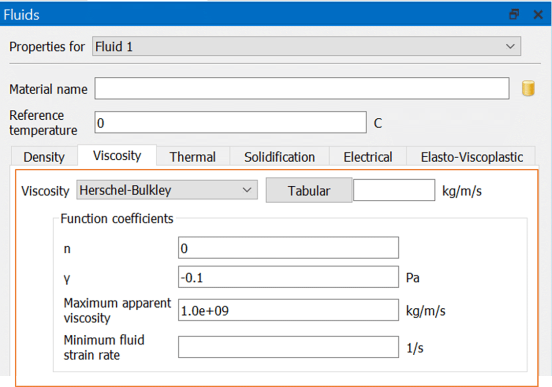
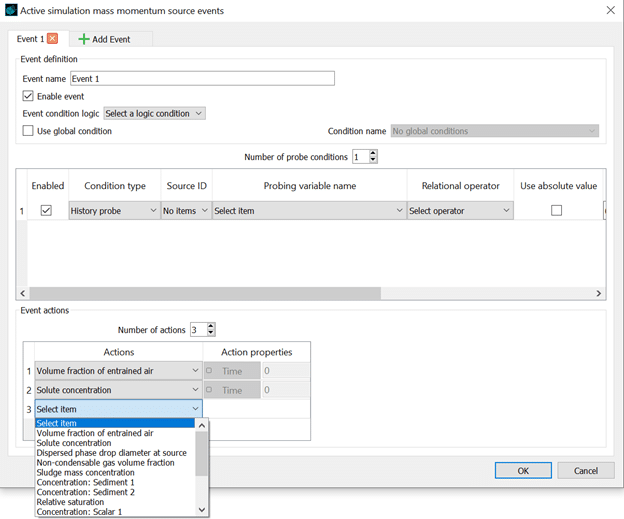
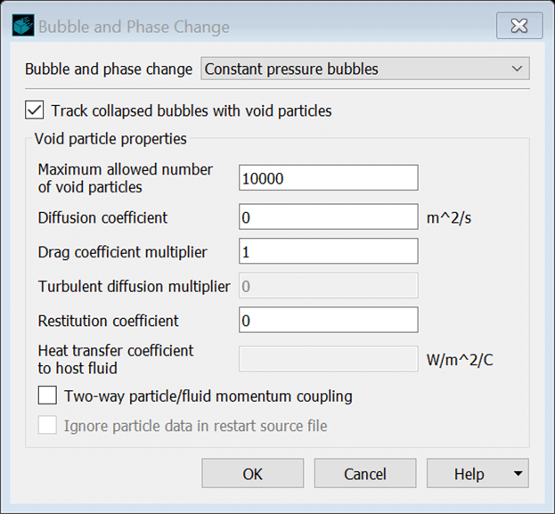
Additional solver features include a Herschel-Bulkley model for non-Newtonian fluids and gas-to-void conversions to improve mass conservation for fluid regions subject to breakup, and extended mass-momentum source probe events, including support for multiple event actions and event options for volume fraction of entrained air and solute concentration.
GUI Improvements
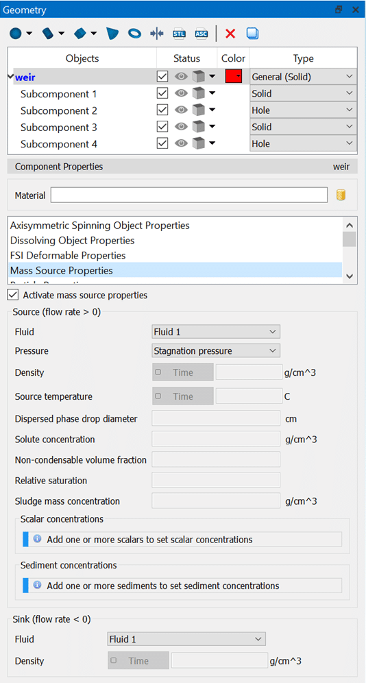
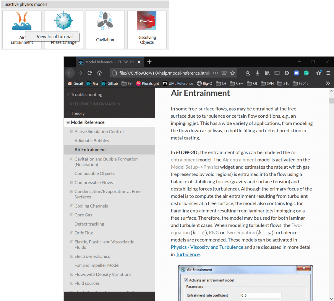
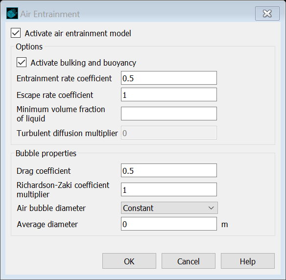
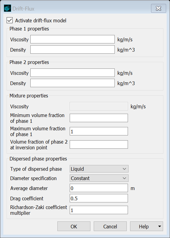
Streamlined GUI improvements using our WSIWYN design approach include redesigned physics and initial condition dialogs, and re-designed output and geometry widgets for easier, faster and error-free simulation setup.
Initial Conditions Widget
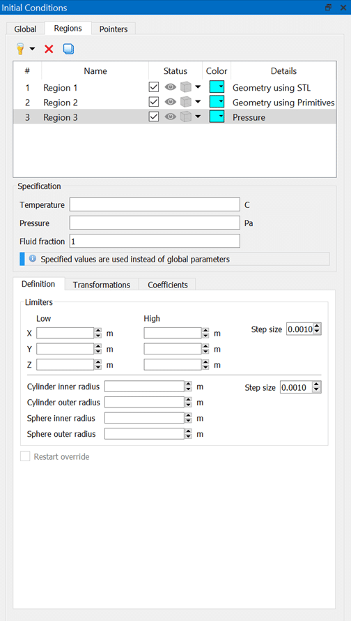
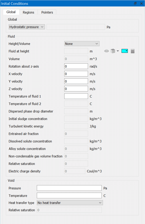
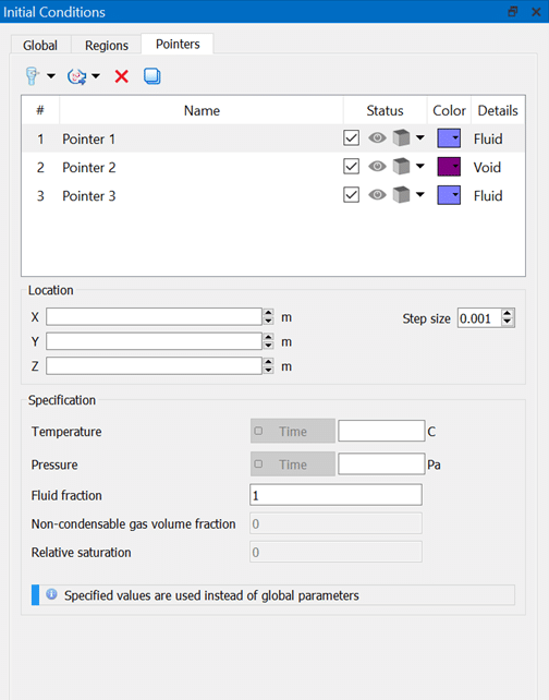
The initial conditions widget improves the setup of initial fluid and gas regions, making it easier and faster. In the new design, global, region, and pointer objects are placed in separate tabs, allowing a much clearer view of the setup.
Output Widget
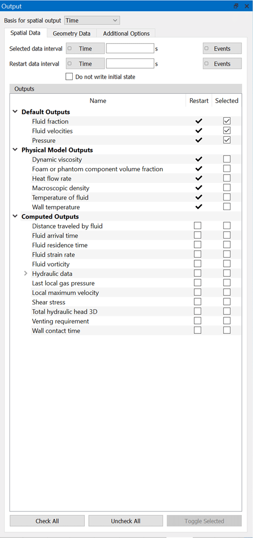
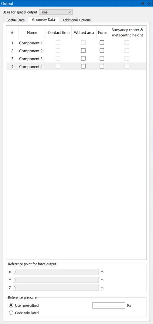
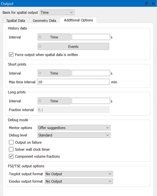
The redesigned output widget lets the user see exactly which outputs will be available in the simulation results file, clarifying restart and selected data outputs in one concise view.
Interactive Geometry Creation and Editing
Interactive geometry creation and editing is better than ever, and now includes:
- New interactive tool selection including rotate, move and resize
- Enter rotate, move, or resize mode by clicking the action and selecting the geometry to modify
- Clicking the up arrow icon or hitting the ESC key will return the user to a normal select mode
