


FLOW-3D CAST Playlist
Entrained air & gas pressure within improvised HPDC runner above shot sleeve radius | FLOW-3D CAST
0:26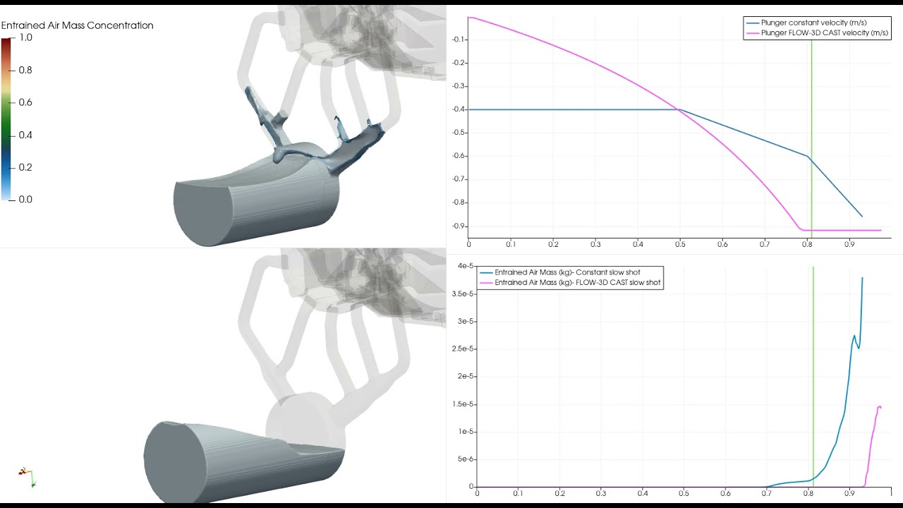
Comparison of slow shot profiles and entrained air during a HPDC filling simulation |FLOW-3D CAST
0:44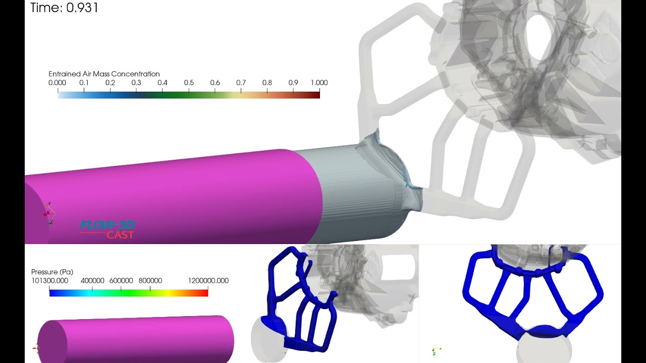

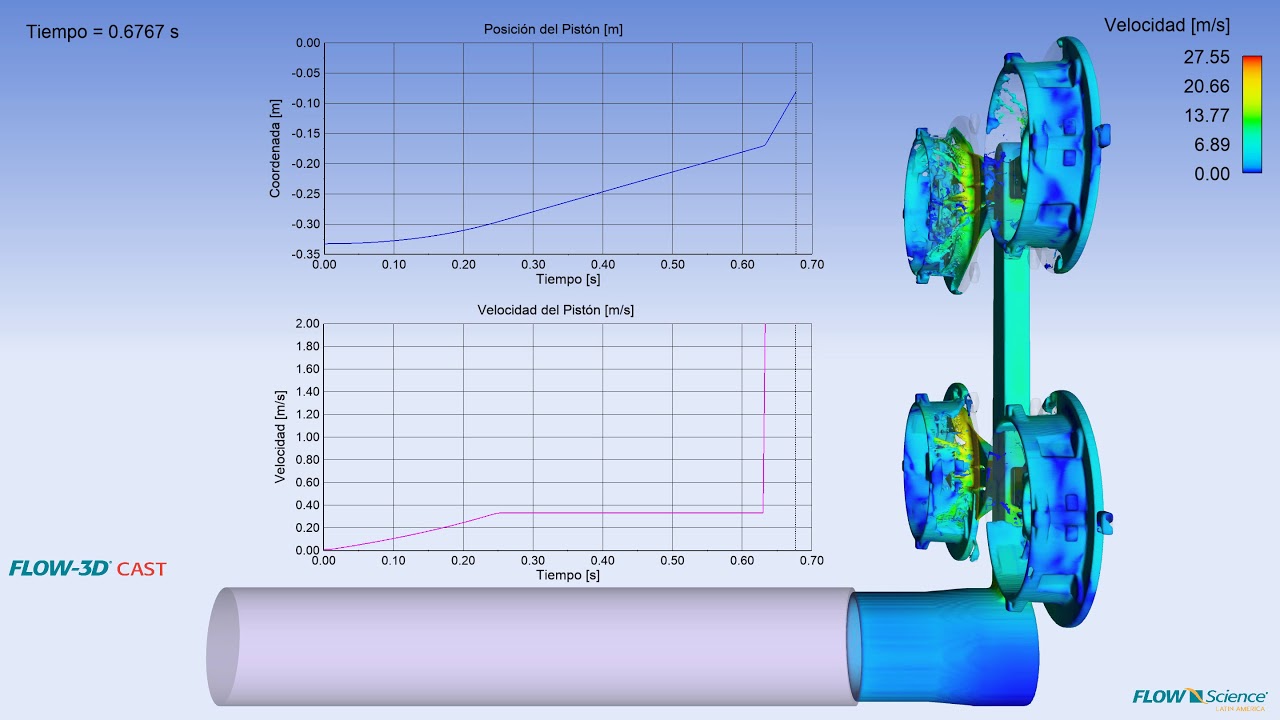


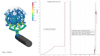
This video demonstrates Active Simulation Control being used to increase data output frequency when fast shot begins so that flow details can be captured. Flux surfaces are placed at the gates to measure the average velocity. When the average velocity exceeds 35 m/s, Active Simulation Control sets the output frequency to 0.0007 seconds for the duration of the simulation.
This simulation illustrates how bad runner design leads to excessive air entrained in runner, premature fill of the bell housing cavity and potential mistimed transient/fast shot. FLOW-3D CAST can help you determine the cause of problems in your casting design and how to improve it before costly mistakes happen.
This simulation shows a comparison of two high pressure die casting runner designs originating at different points off the biscuit. The video shows air mass concentration and air pressure bubbles within the runner.
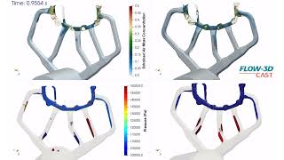
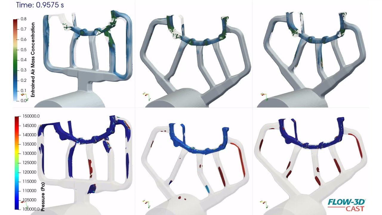
Three runner designs are compared during a high pressure die casting slow shot of a bell housing simulation. Air mass concentration and air pressure bubble color scales indicate progressive design improvement, from runner on left to runner on farthest right, with respect to runner air entrainment.
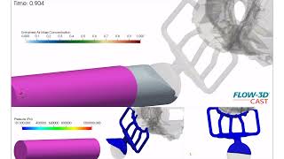
This simulation shows a high pressure die casting runner design originating above the biscuit, entraining relatively less air. The video shows air mass concentration and air pressure bubbles during slow shot of a bell housing fill simulation.
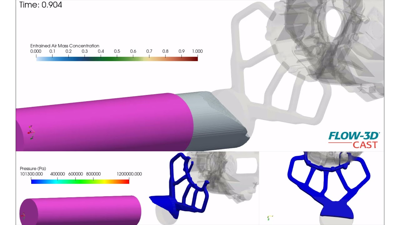
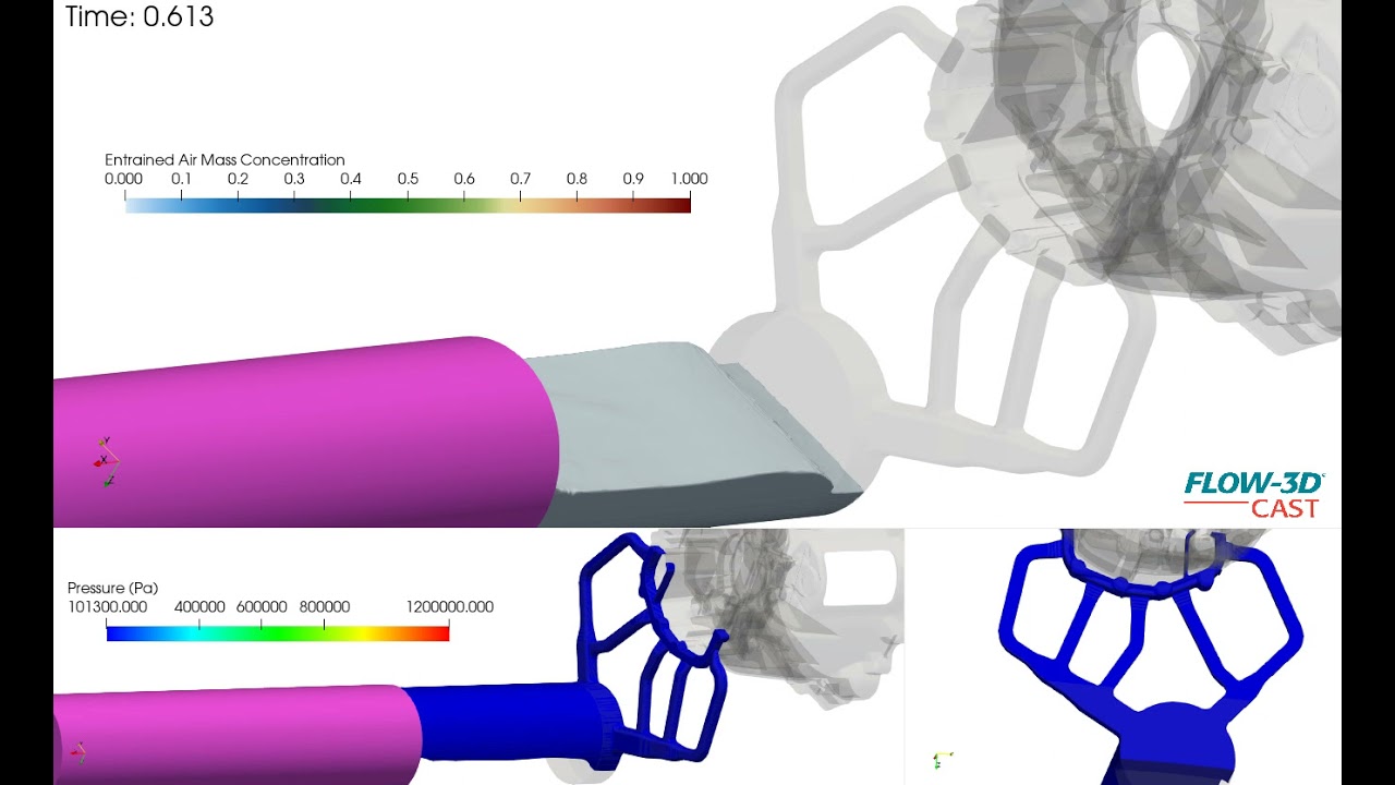
This FLOW-3D CAST HPDC simulation compares two slow shot profiles. The graphs highlight the shot profiles through time and the difference in entrained air between the slow shots. Note the lack of air entrained in shot sleeve with calculated shot profile which yields a much better controlled flow within the shot sleeve.
This FLOW-3D CAST simulation describes a calculated controlled slow shot profile entraining less air. There is minimal wave topping and disturbance to flow in shot sleeve. Some air is entrained near biscuit and through runner, however much less in comparison to constant speed slow shot profile. The video shows air mass concentration and air pressure bubbles during slow shot.
This FLOW-3D CAST HPDC simulation highlights a constant velocity slow shot with multiple stages that result in unwanted air bubbles within shot sleeve. These bubbles are transferred through runner into the casting. Notice how the metal wave laps over and topples in shot sleeve, entraining a lot of air that moves through runner before fast shot. Also, the momentum of metal is different in runner as air bubbles influence metal volume and path in runner, irrespective of runner design. Some of this air can likely be forced out of the casting through intensification pressure, but it is highly undesirable and can be avoided with a better shot profile acceleration input. The video shows entrained air mass concentration colored over metal volume and air pressure (open regions), while air bubbles are entrained in slow shot.
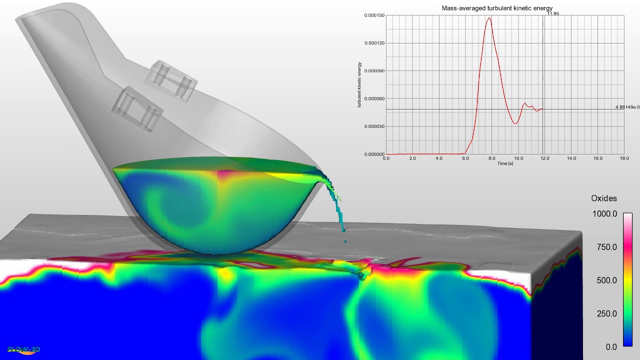
FLOW-3D CAST allows the user to model and compare ladle shape, ladle motion with 6 degrees of freedom, surface oxide formation and transfer into the ladle pour.
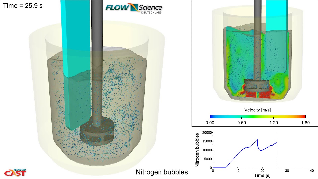
The mechanical properties of aluminum can be negatively affected by dissolved hydrogen in the metal. To mitigate this, a rotary degassing process introduces an inert purge gas (in this case, nitrogen) into the melt. The circulation created by the rotor allows the hydrogen to diffuse into the inert gas bubbles. FLOW-3D CAST allows the process engineer to model process parameters such as rotor design and speed to achieve optimal mixing and cast quality.
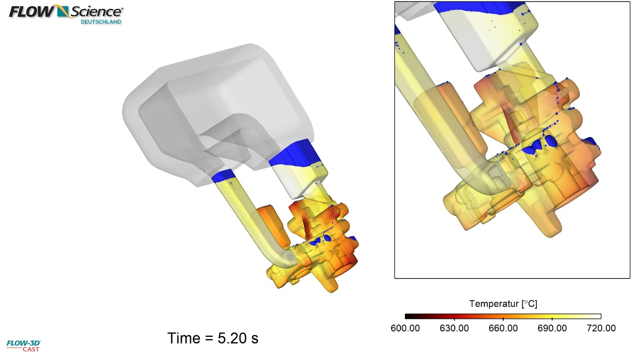
FLOW-3D CAST allows process engineers to accurately model the full high pressure die casting process, from ladle pour through solidification. This simulation shows the air entrained in the shot sleeve traveling into the mold. Key framing provides 360° views of the fill.
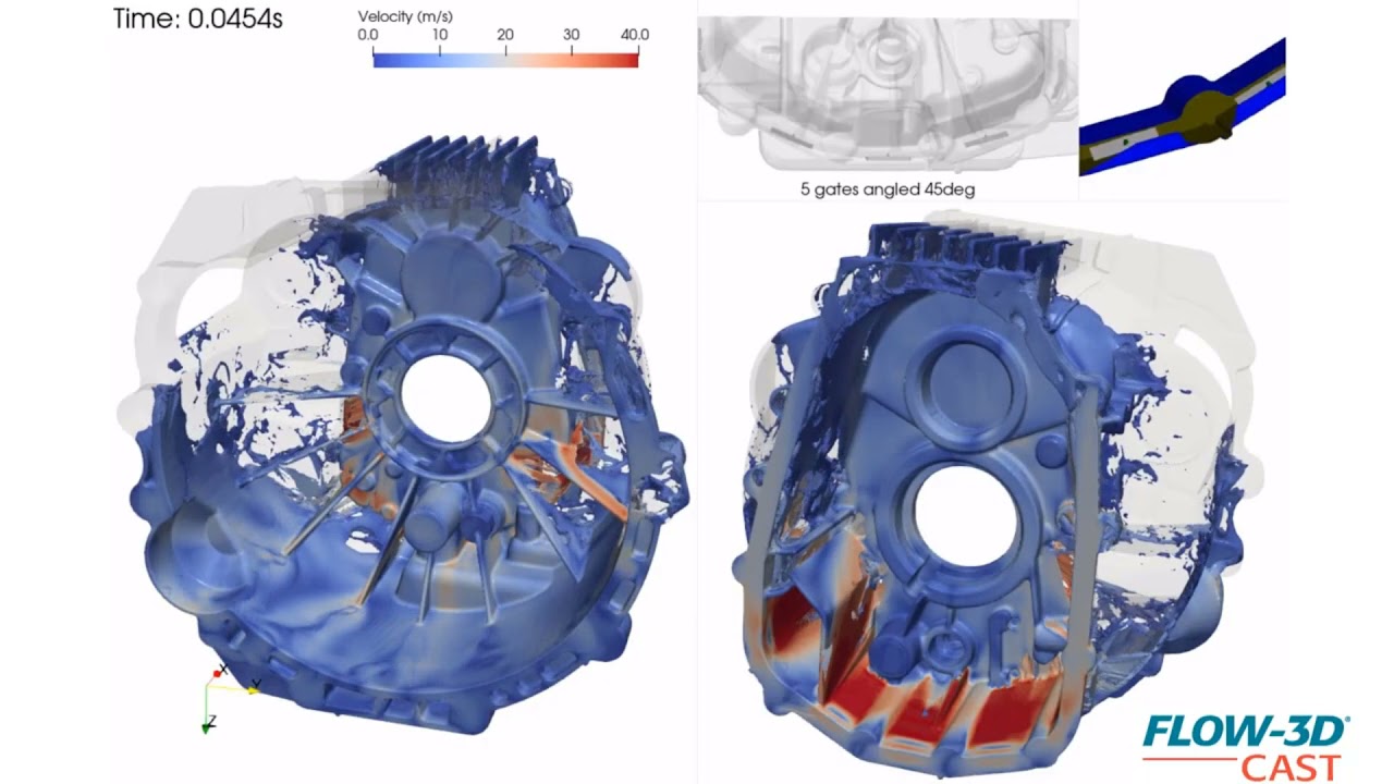
This is a simulation of an automotive flywheel or bell housing, showing velocity contours of an aluminum alloy during a fast shot of a high pressure die casting process. It is part of a design phase to evaluate different gating options. In this simulation, gates are angled at 45 degrees. The comparison between this and other gate angles helps visualize the effect of gates on this highly turbulent fill before addressing runner designs.
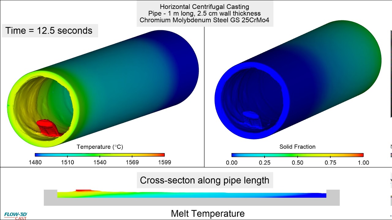
This simulation shows pouring a centrifugal casting of a horizontal pipe. The focus of this simulation is analysis of the filling pattern. The objective of the simulation was to prevent wall separation and have a smooth filling which did not trap air.
This simulation shows the production of door handles using the hot-chamber zinc die casting process. In zinc casting, there is a high technical requirement for the foundry to avoid production-related defects and discontinuities on the surfaces as best as possible. Simulations are a powerful tool for designers and foundrymen who want to achieve high casting quality. In FLOW-3D CAST the thermal die cycling process, mold filling and solidification can be accurately modeled, so that errors and problems during casting can be detected and avoided.
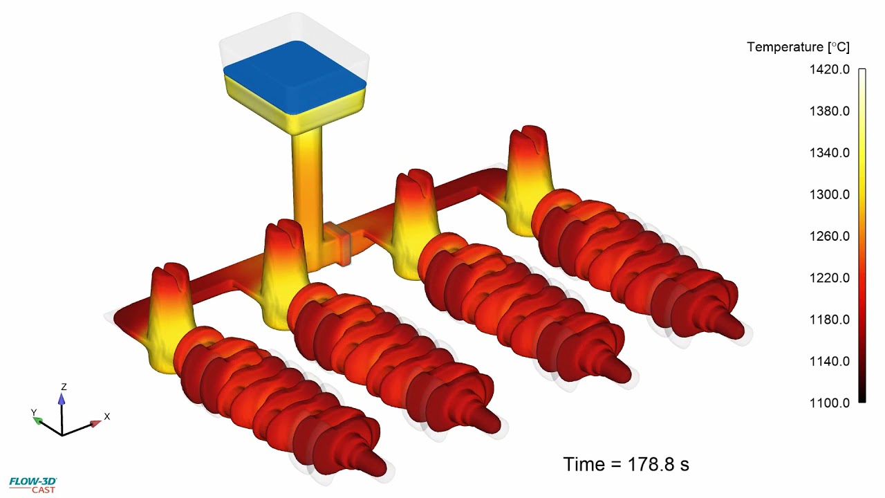
This simulation shows the filling of a planetary carrier with a ladle. The complete process from filling to solidification can be simulated with FLOW-3D CAST, including chills and exothermic risers, allowing for accurate prediction of casting defects and ensuring the best possible casting design.
This simulation illustrates the filling and solidification of ductile cast iron crankshafts, which was used to investigate a directional solidification into the risers. FLOW-3D CAST can be used to predict and avoid casting defects. Accounting for factors in cast iron including carbon expansion, primary (open) shrinkage cavities and secondary (internal) shrinkage cavities can be reliably displayed. Based on the size and position of the defects, the necessity of improvements to the casting design can be determined.
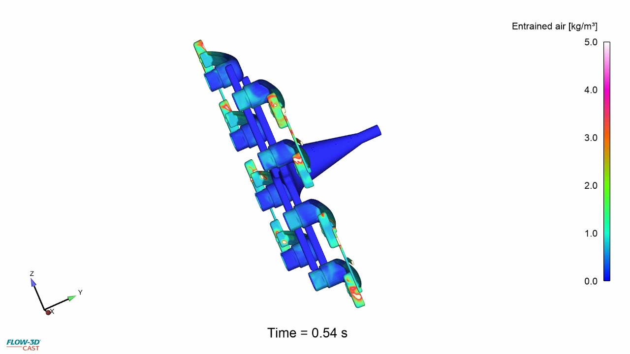
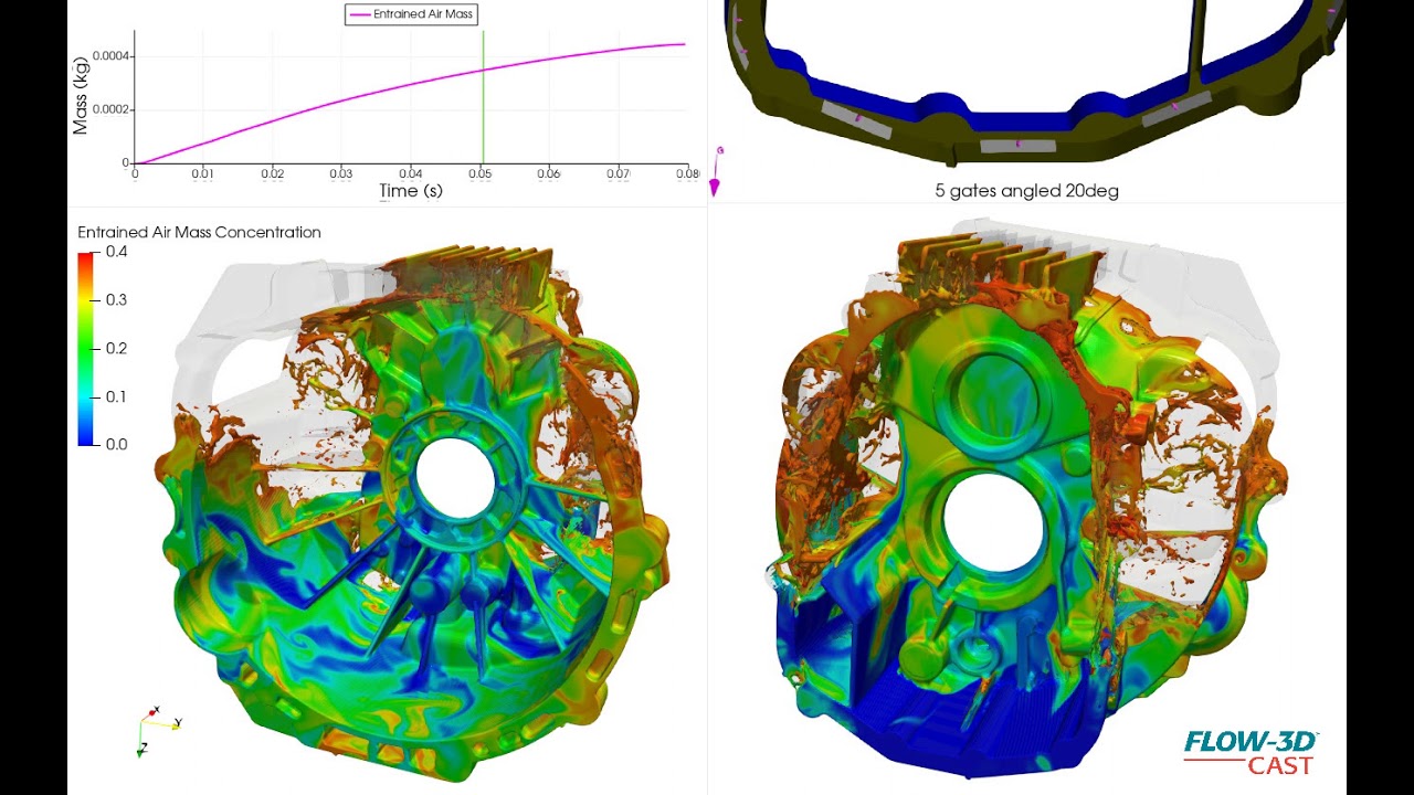
This is a simulation of an automotive flywheel or bell housing, showing air entrainment of an aluminum alloy during fast shot of high pressure die casting process. It is part of a design phase to evaluate different gating options. In this simulation, gates are angled 20 degrees, the contours indicate entrained air mass concentration.
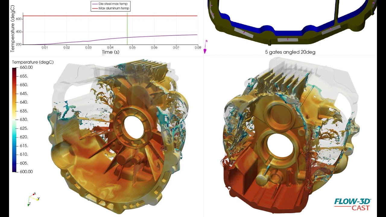
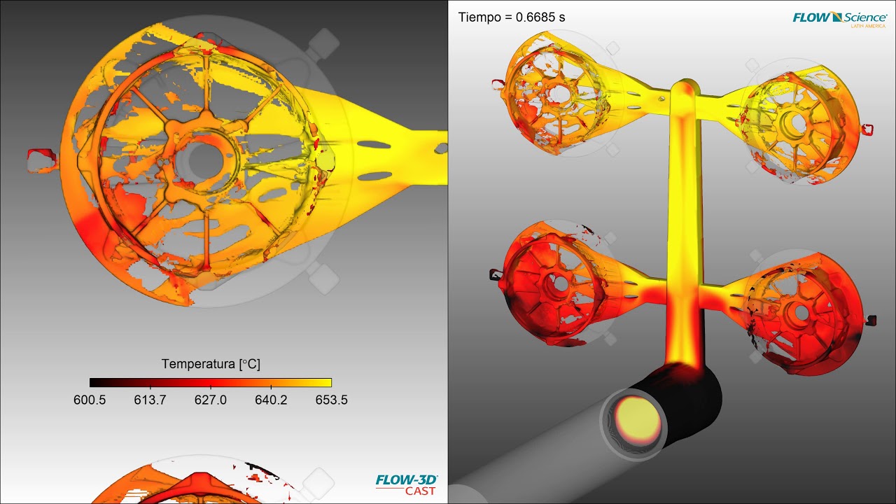
This is a simulation of an automotive flywheel or bell housing, showing thermal gradients during filling stage of a HPDC fast shot process.
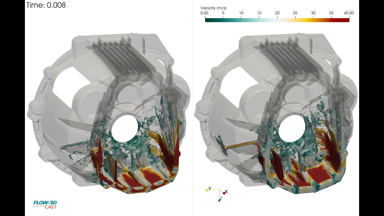
This is a simulation of an automotive flywheel or bell housing, showing velocity contours of an aluminum alloy during a fast shot of a high pressure die casting process. It is part of a design phase to evaluate different gating options. Shown here is a comparison of five gates, simulating filling from a runner below the parting line to accomplish an 80-millisecond casting fill. The left-hand simulation in the video shows gates pointed upward below the parting line, while the right-hand simulation shows gates at the same location, angled at 45 degrees.
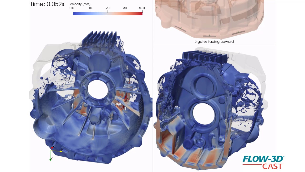
This is a simulation of an automotive flywheel or bell housing, showing velocity contours of an aluminum alloy during a fast shot of a high pressure die casting process. It is part of a design phase to evaluate different gating options. In this simulation, gates point upward below the parting line. The comparison between this and other gate angles helps visualize the effect of gates on this highly turbulent fill before addressing runner designs.
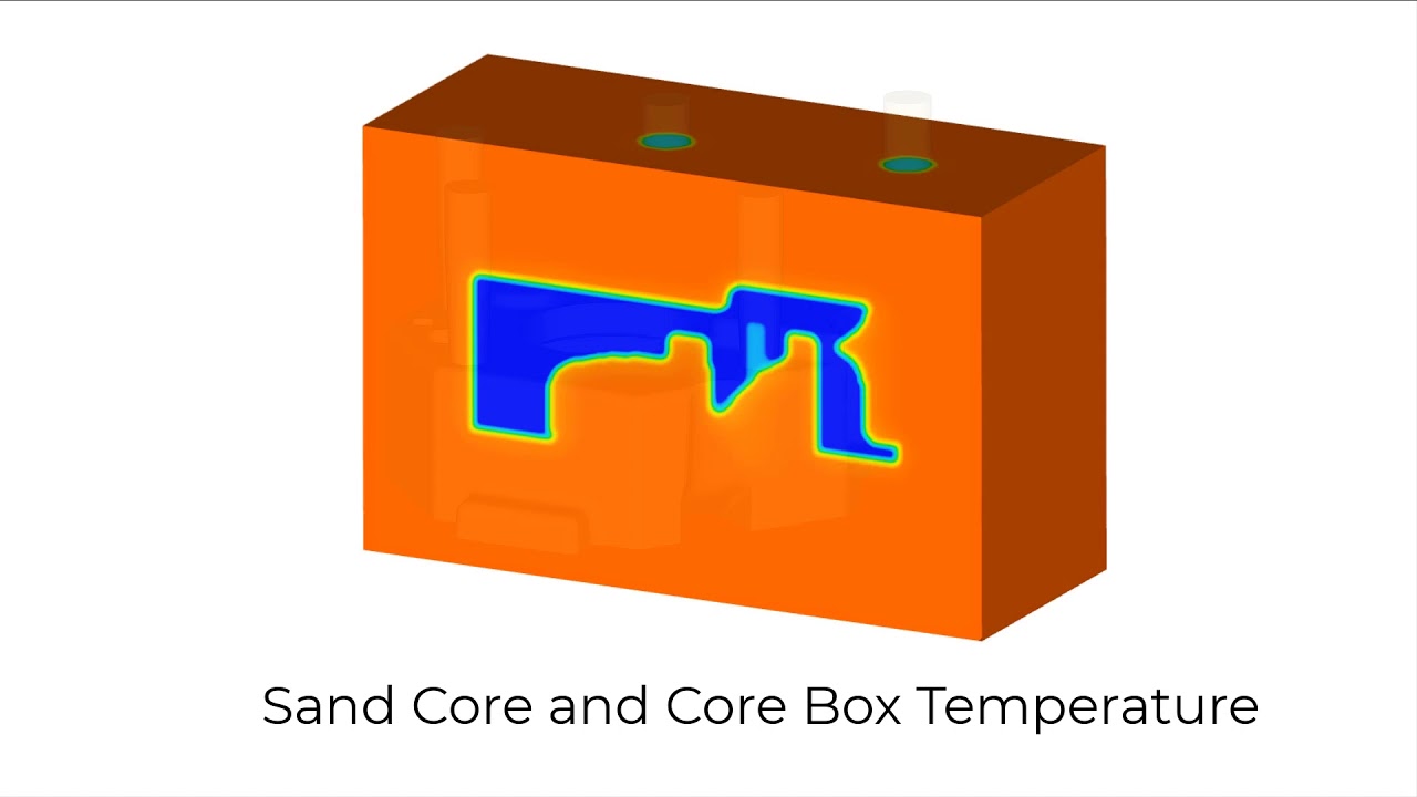
Sand cores shot in a hot box process are hardened using energy from the core box to cure the binder. This video shows the temperature distribution in the sand core as it is heated by the hot core box.
This video shows the filling pattern of H32 sand with a 2% binder additive being shot to produce an water jacket sand core. Notice that some of the regions are underfilled.
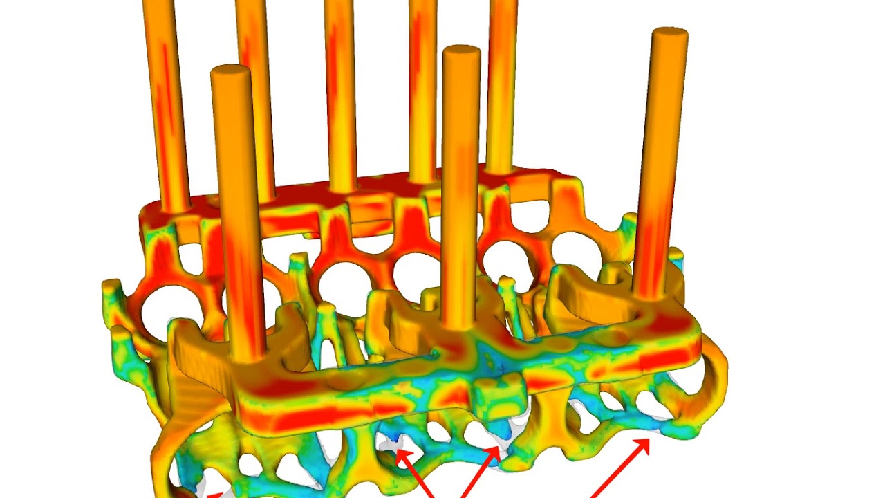
This FLOW-3D CAST simulation shows the evolution of amine gas through the porous, shot sand core, which is a water jacket for an internal combustion engine.
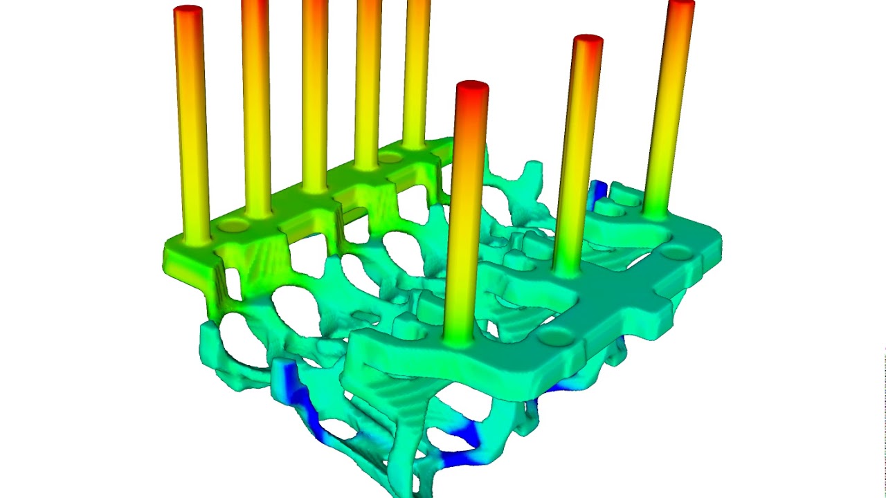
In this FLOW-3D CAST simulation, an intake manifold sand core shot with a sand/binder mixture containing 2% water by weight is dried by a hot (180 C) air purge. The blue region represents the water remaining in the sand core. The air vents are shown in gray. After 150 seconds of drying, the moisture continues to be pushed to the area where the most venting.
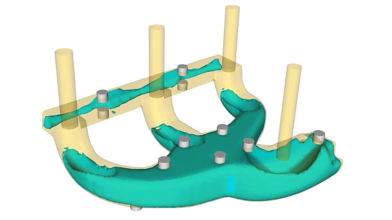
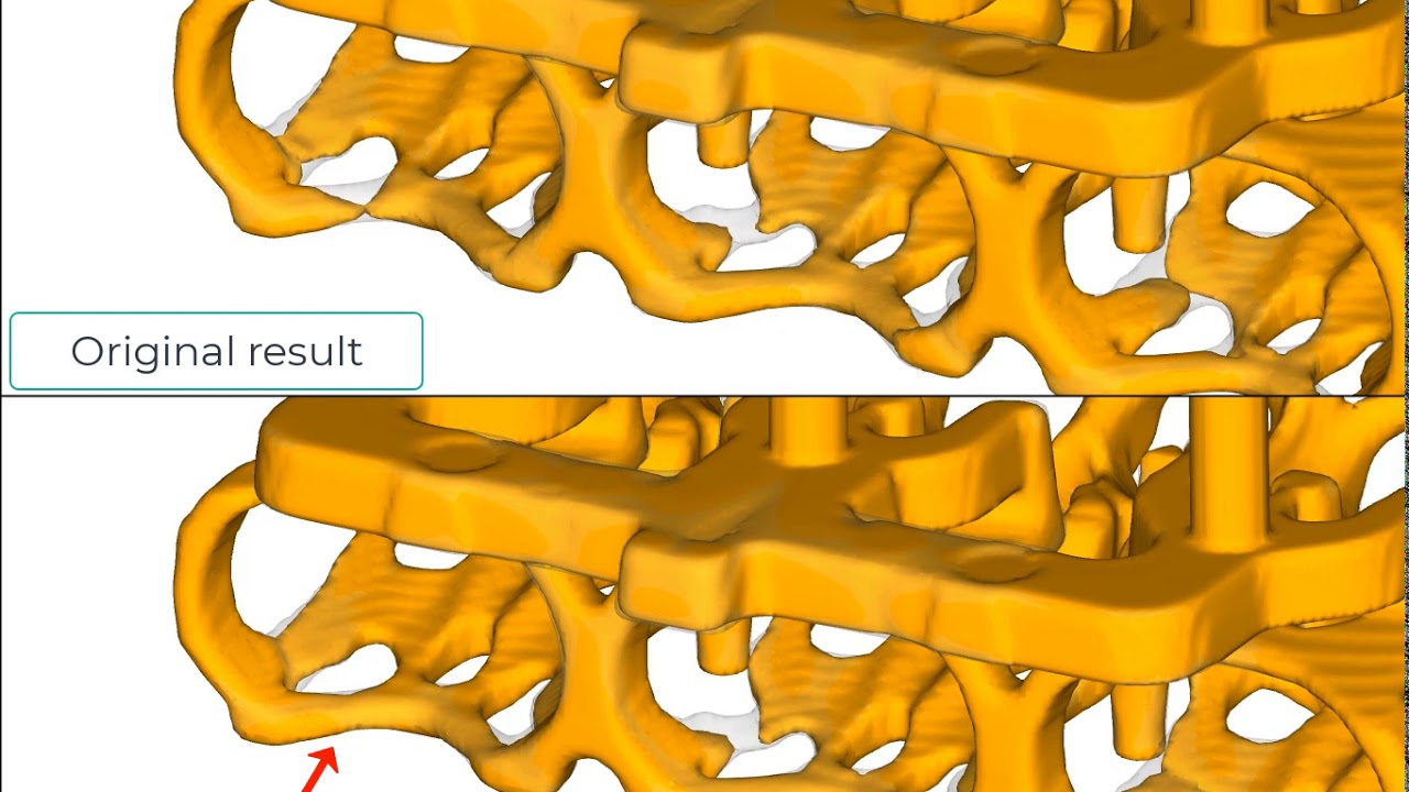
This FLOW-3D CAST simulation shows a comparison of the filling in the region where the air vent was added compared with the original result. The filling is now more complete in the region where the air vent was added. More vents can be easily added to address other underfilled regions.
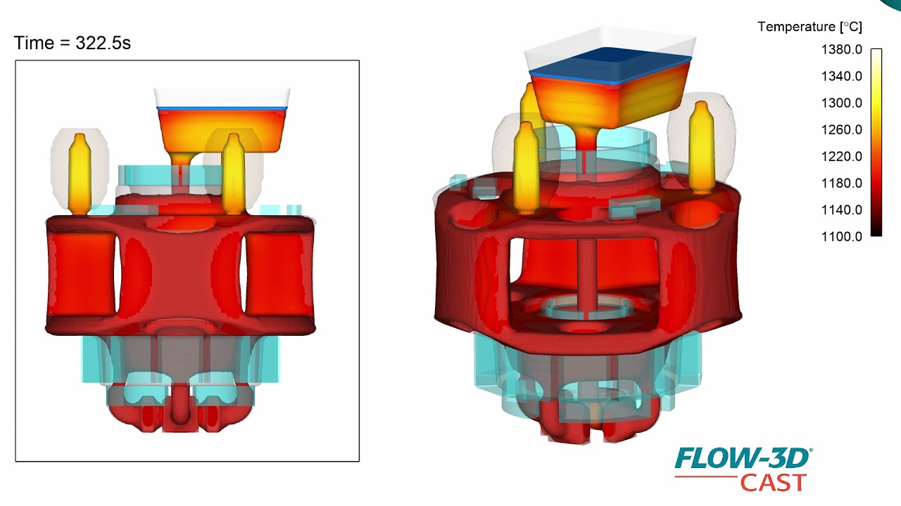
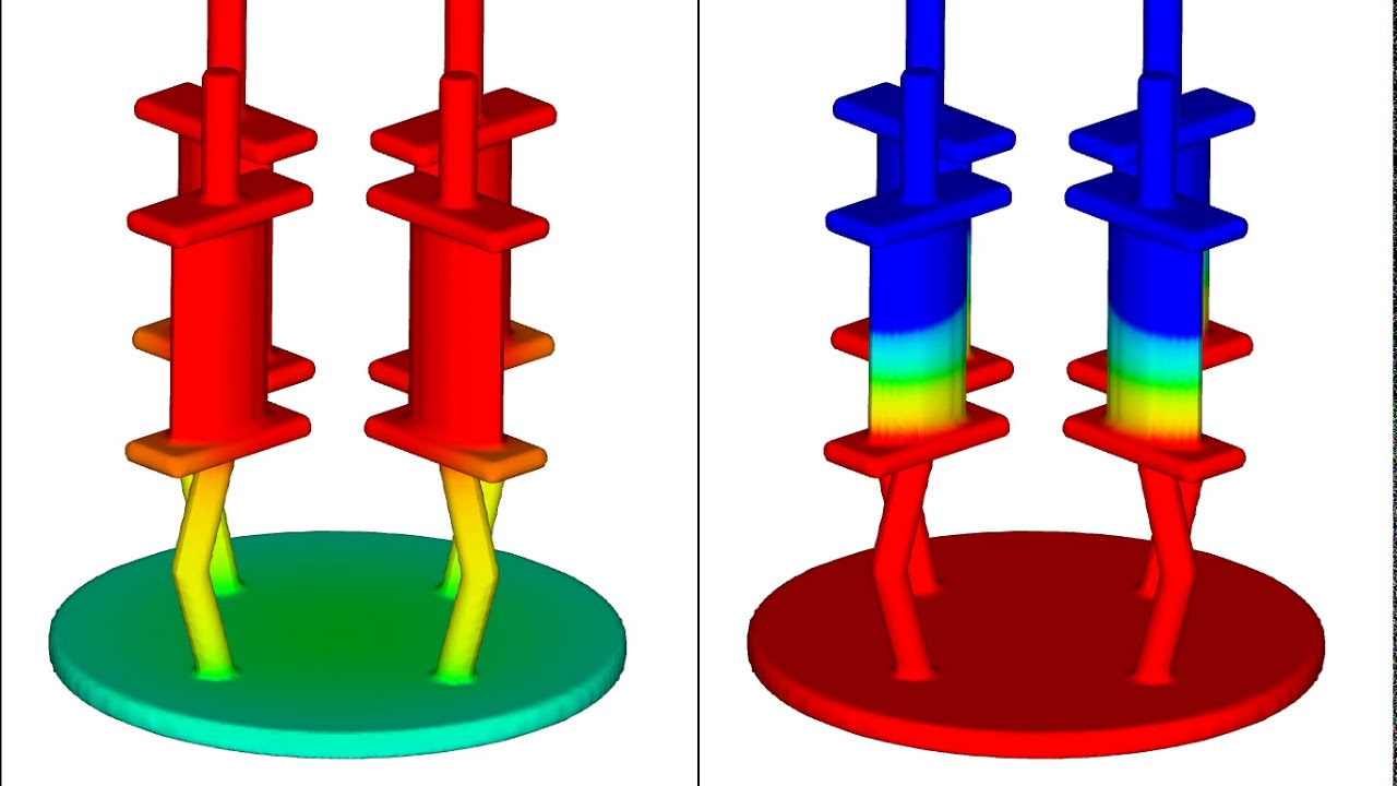
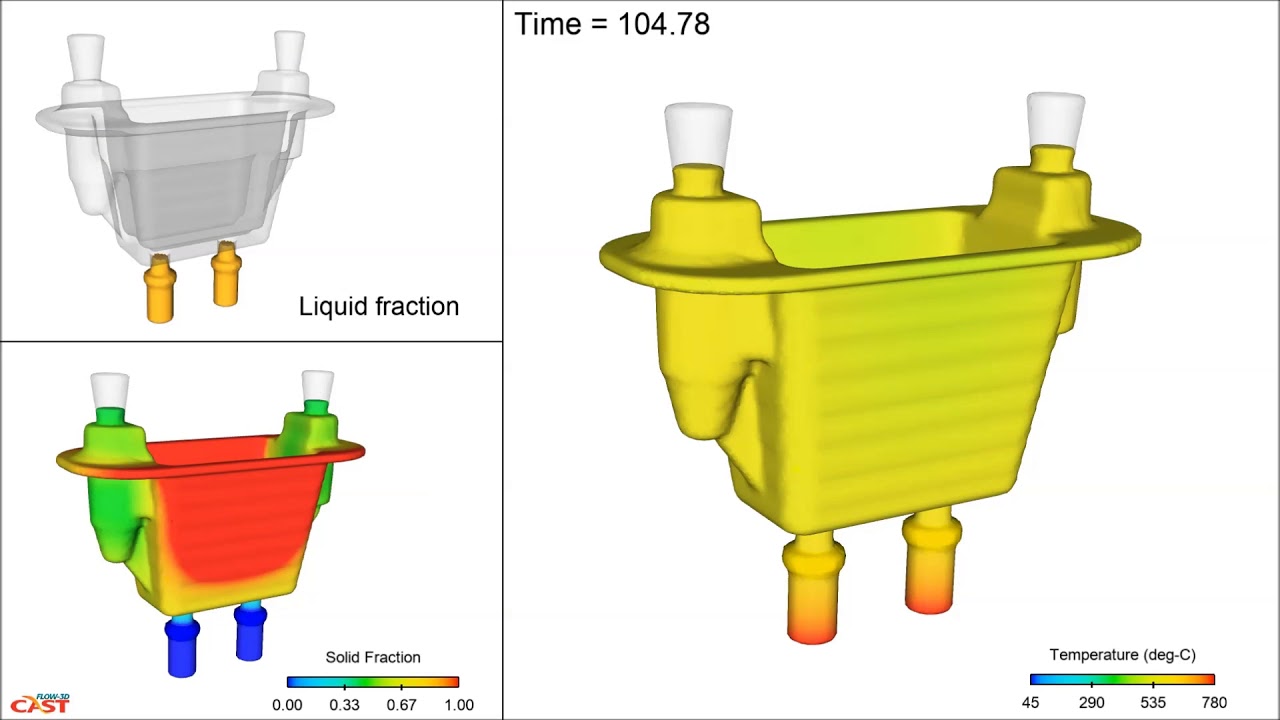
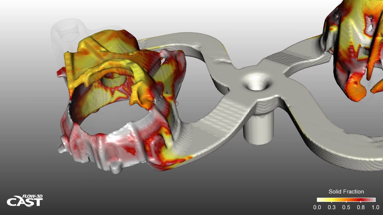
This simulation shows how the temperature distribution in the solidifying casting on the left and the solid fraction on the right. The feeders at the top of each part provide liquid metal to the casting as it solidifies and shrinks.
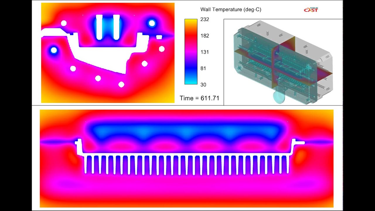
This FLOW-3D CAST simulation is a cross-sectional view of the die components during the entire tenth, and final, cycle. For this thermal die cycling analysis there were 6 stages in each cycle: 1. Solidification, 2. Ejection, 3. Open, 4. Blow Air, 5. Spray lubricant, 6. Closed, and we ran 10 total cycles. On the shop floor this would translate to 10 “shots” in order to develop this temperature profile. Notice the cooling profile at the parting lines, which are the horizontal contours, and how they change with time.
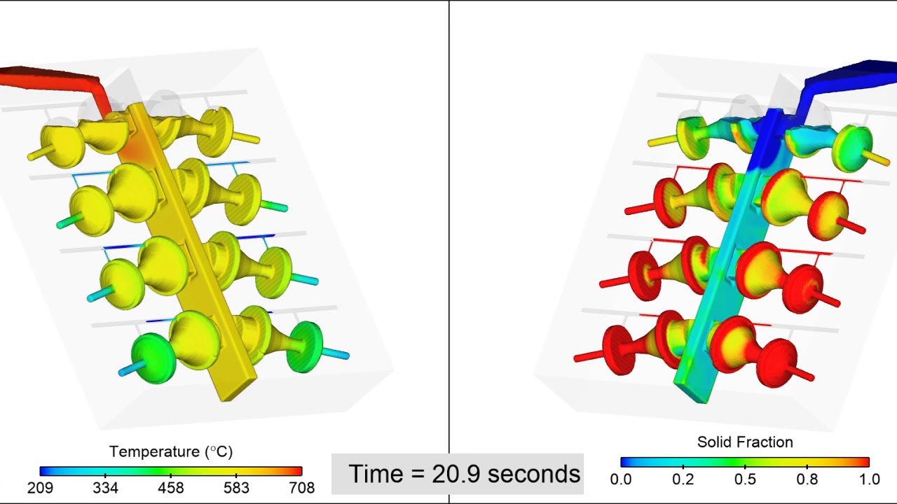
In this tilt pour casting of an aluminum ornamental fixture, the ladle is preheated to 500 C and is filled with Aluminum A356 at 708 C. The mold, made of H13 steel, is preheated to 200 C. The mold and ladle are rotated from horizontal to about 15 degrees from vertical allowing the melt to flow in a controlled fashion into the mold cavities. Air vents are placed on the mold cavities to allow air to escape. This simulation shows the temperature distribution in the melt and the solid fraction evolution as the mold cavities fill.
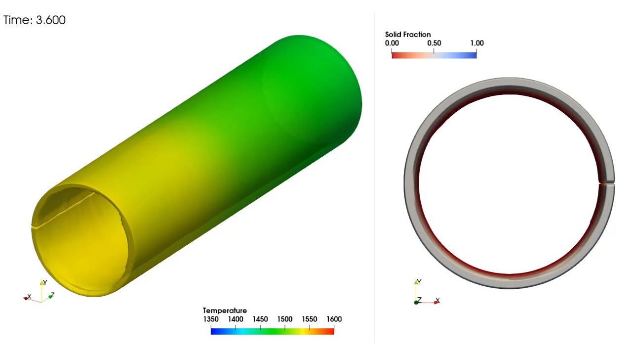
This simulation represents the filling stage of a pipe casting manufactured using a horizontal centrifugal casting process. The pipe is cast with Chromium Molybdenum Steel GS 25CrMo4 and is 1 m long and 2.5 cm wall thickness. The goal of casting pipes is to ensure that the thickness is uniform along its length. The cross-sectional view at the bottom of this video shows the distribution of the melt along its length. The melt should be uniformly distributed before solidification begins. Simulation can be used to study the impact of the initial temperature of the mold, the pour temperature, and the pour rate on the solidification during fill. Another important process parameter is effect of the mold rotation rate (500 rpm in this case) on the distribution of melt along the mold length. If the mold rotates too slowly, the melt will not pick up speed quickly enough to keep it attached to the mold surface resulting in raining which can cause production to stop for a significant period of time while the mold and the shop floor is cleaned.
An important process parameter for controlling air entrainment in HPDC is the velocity profile of the shot plunger. Various plunger velocity profiles can be studied in FLOW-3D CAST to identify the amount of air entrainment for each. Additionally, a slow shot velocity profile calculator is included which helps to quickly estimate the best shot profile for minimizing air entrainment. Results analysis tools in FLOW-3D CAST provide a number of views of entrained air that make comparing the results of various shot profiles quick and easy. A global view of total entrained air is available as well as user-specified sampling volumes which allow local casting regions to be analyzed.
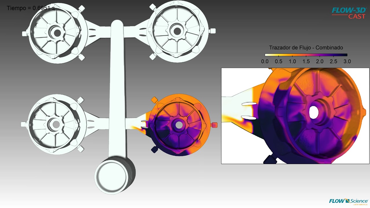
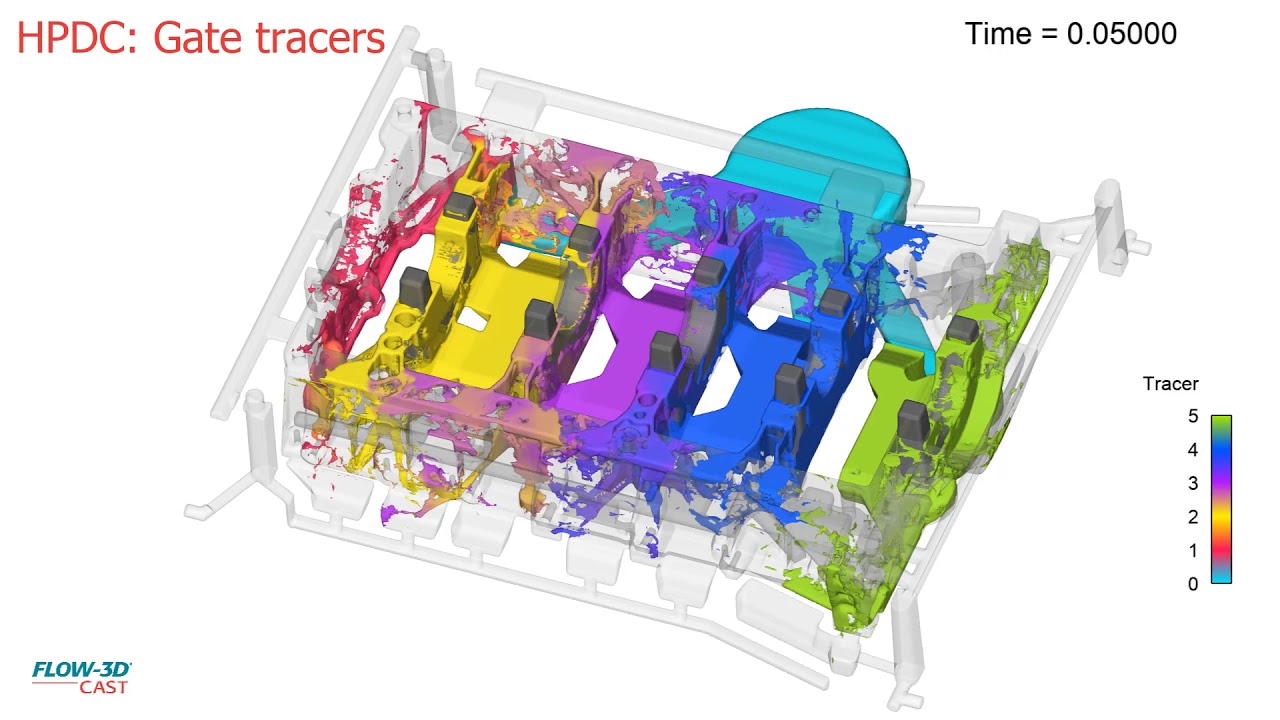
When designing the gating for an HPDC die, it is useful to understand the contribution of each gate to the overall filling pattern of the casting. Ideally, a well balanced filling with each gate filling the casting without significant cross flow will result in the best quality casting. FLOW-3D CAST provides gate tracers which color the melt based on which gate it entered the casting from.
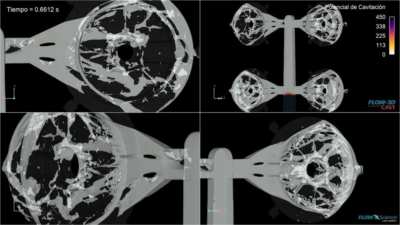
Because of the high velocities and accompanying low pressures created in HPDC processes, cavitation is possible. Cavitation bubbles collapsing on the die surface can create pitting which in turn causes surface quality issues on the casting as well as drastically shortening the life of expensive dies. The cavitation potential model in FLOW-3D CAST is a powerful tool for identifying areas on the die where cavitation is likely to occur. Rather than providing instantaneous indications of cavitation, which are not necessarily problematic, the cavitation potential model provides an overall estimation of the potential for cavitation damage by integrating the duration of the cavitation at each location on the die surface over the fill time.
Maintaining a melt temperature above the liquidus temperature is important in HPDC processes to prevent cold shuts and other defects. FLOW-3D CAST utilizes the most accurate filling simulations in the industry. With accurate filling simulations at their disposal, casting process engineers can identify pour temperature and die temperature profiles that minimize early solidification issues in designs.
FLOW-3D CAST provides users with many ways to instrument their casting simulations to provide a deep understanding of the behavior of their designs. This video shows the use of history probes placed in the gates to gain insight into the flow balance between gates. This information is very helpful, especially in multi-cavity castings where the flow between casting cavities varies.
This FLOW-3D CAST HPDC simulation of a rotor shows the filling profile with the addition of the shot sleeve dynamics.
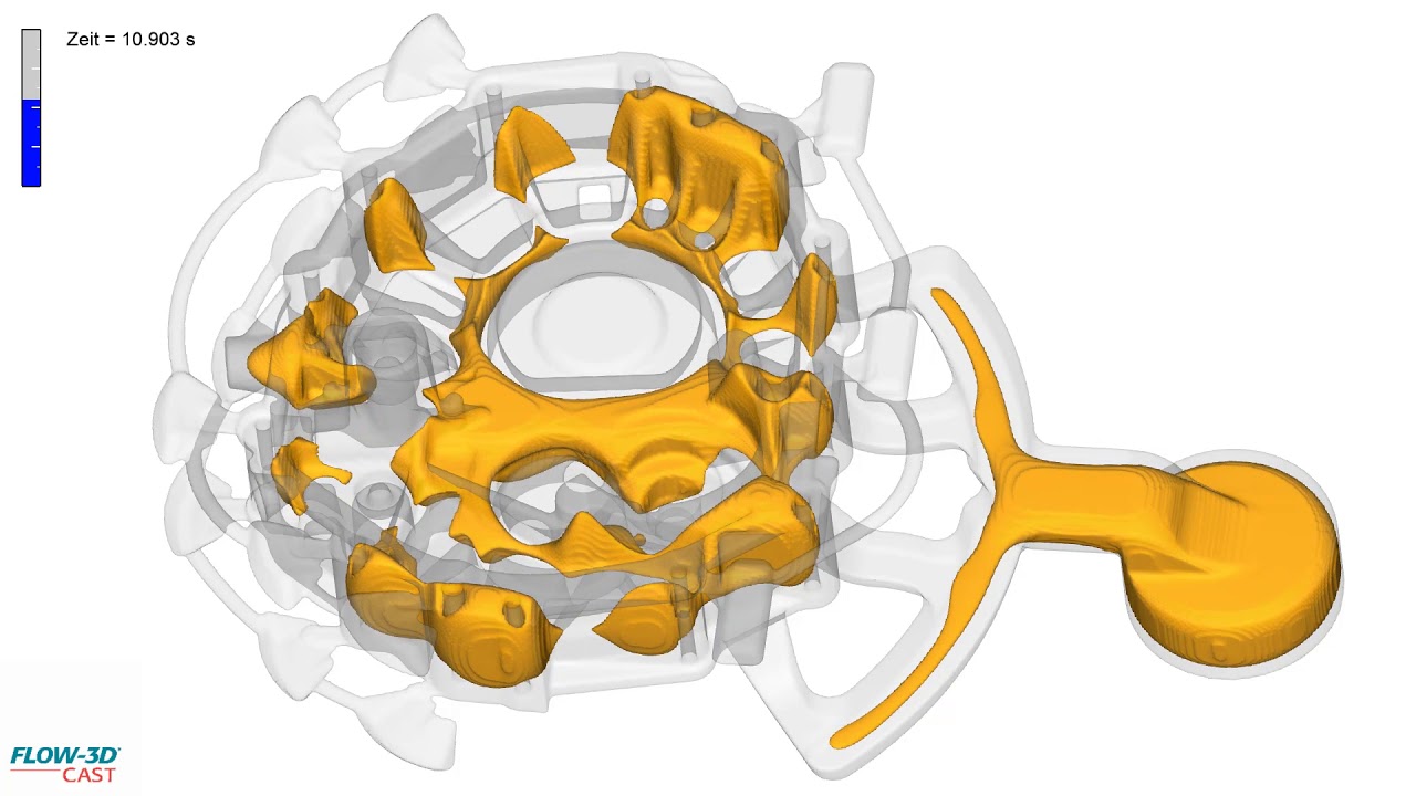
This FLOW-3D CAST simulation of a complex thin walled casting geometry shows the propagation of the solidification front.
This FLOW-3D CAST filling simulation of a complex thin walled part with salt cores shows the use of gate tracers to visualize rigging performance.
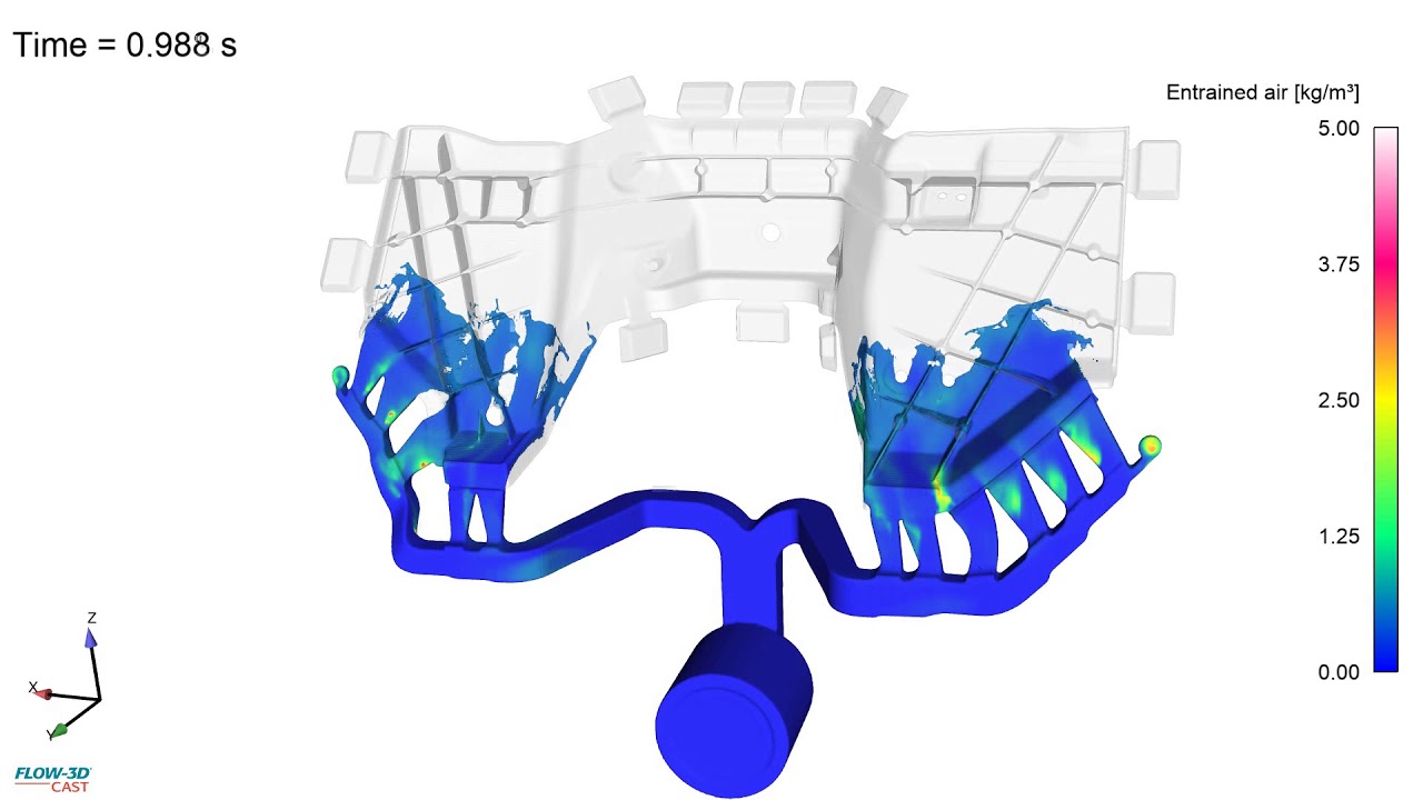
This FLOW-3D CAST filling simulation of a complex thin walled part shows the air entrainment variable to understand where defects can become an issue in the filling process. Visualization of air entrainment can be used to understand die venting, back-pressure, and areas of porosity.
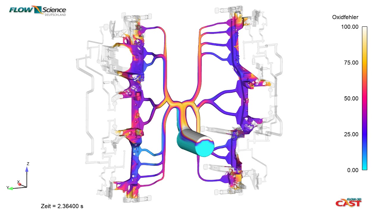
This FLOW-3D CAST filling simulation of an automotive component visualizes the oxide formation variable to understand where defects can become an issue in the filling process.
This FLOW-3D CAST filling simulation of a water pump shows the temperature distribution through a detailed filling pattern.
This simulation using FLOW-3D CAST‘s Centrifugal Casting Workspace represents the vertical centrifugal casting of an aluminum A356 flange. Melt is introduced into the mold via a vertical sprue at a rate of 5 kg/s. The mold is spun about its vertical axis at 500 rpm, providing an outward acceleration of 200 g at the surface of the mold. The left frame shows the pickup of the melt by the mold and helps determine the rate at which the melt distributes vertically over time. The upper right frame shows the solid fraction in the melt; this analysis helps determine the proper mold preheat to avoid premature solidification. In the lower right frame, the entrained air mass concentration is shown. As long as solidification does not occur prior to complete filling, all of the entrained air will be forced to the inner diameter of the casting, to be machined off later.
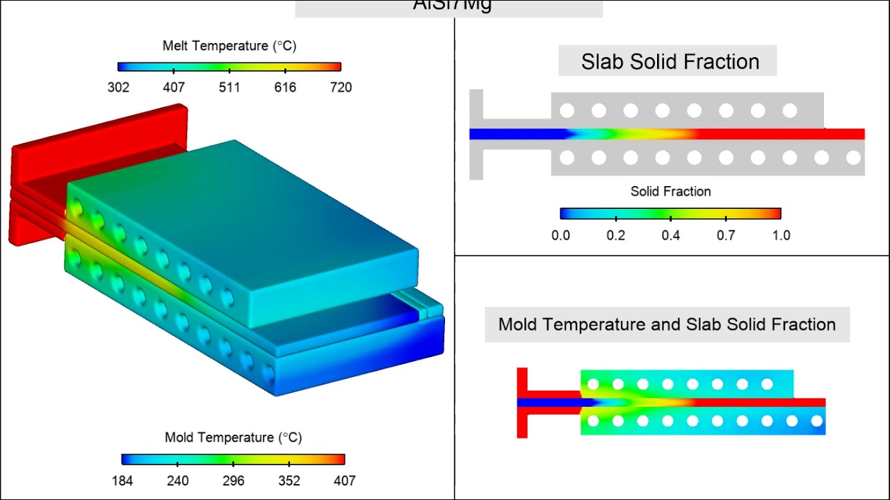
The goal of this simulation is to determine the cooling required to maintain a stable solidification profile during the continuous casting of Aluminum A356 plates. Melt is introduced into the process through a calcium silicate nozzle. Copper-Cobalt-Beryllium molds on both sides of the melt contain cooling channels to draw heat from the melt. The solidifying plate is drawn from the mold at a rate of 8 mm/sec.
The Investment Casting Process Workspace in FLOW-3D CAST v5.1 offers automatic shell generation in addition to advanced radiation modeling, in order to deliver extraordinary accuracy to aid the design modeling process.
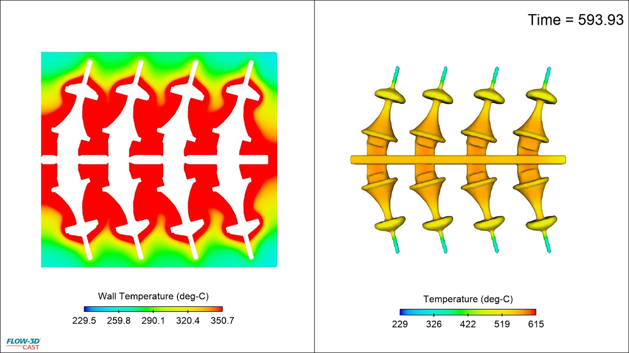
This FLOW-3D CAST thermal die cycling simulation is used to assess the thermal saturation over multiple cycles.
This FLOW-3D CAST filling simulation of a low pressure sand casting mold is used to assess defect propagation in the metal front.
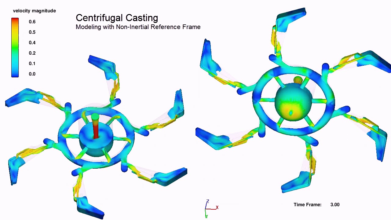
This centrifugal casting filling simulation with non-intertial reference frames allows the user to view the fluid front in the rotating mold. Simulation courtesy of Simulated Engineering.
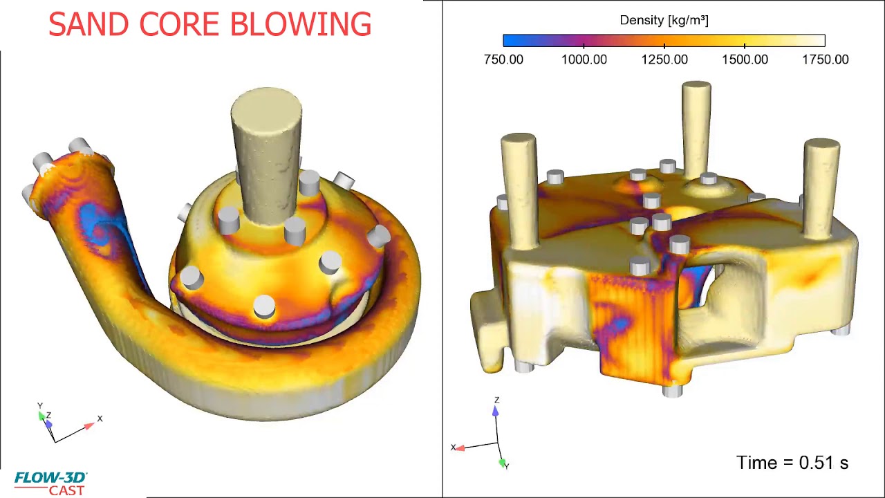
This FLOW-3D CAST sand core blowing simulation of a turbo charger housing is used to assess the density of the sand mixture during shooting.
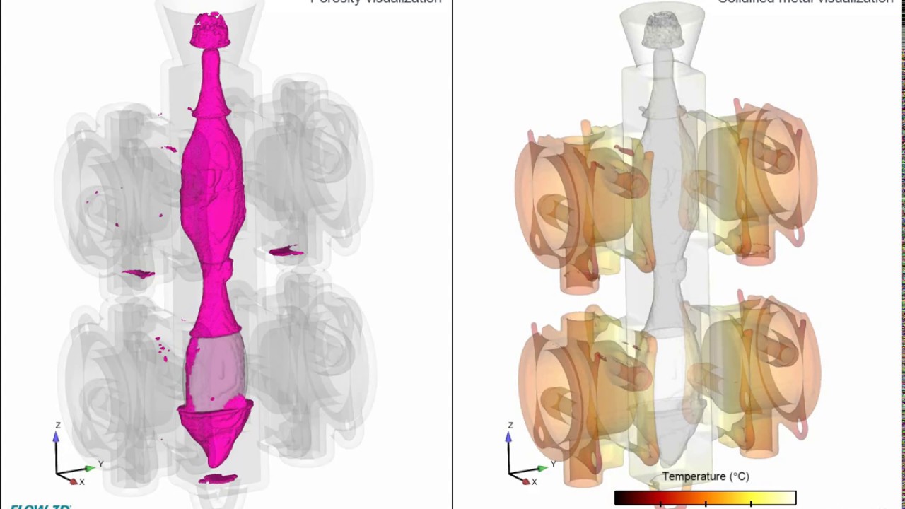
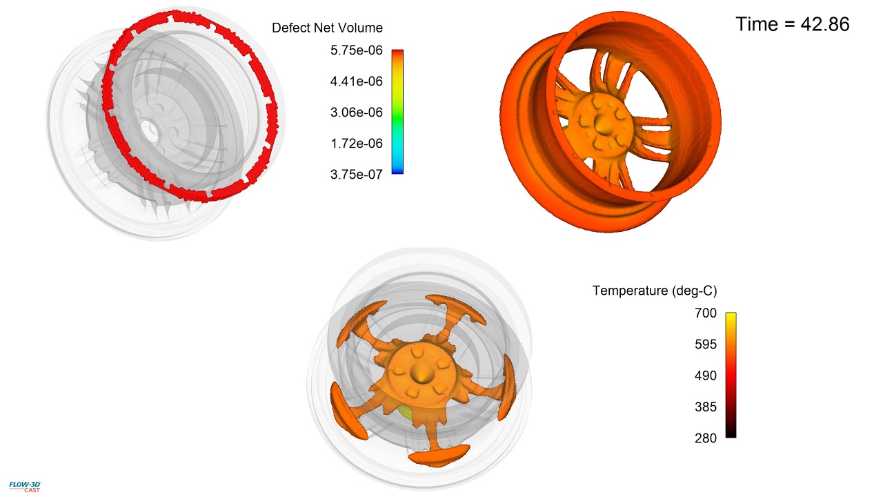
This FLOW-3D CAST simulation of an aluminum wheel low pressure die casting visualizes the solidification front and predicted net defect volume based on porosity. This example is part of a webinar on FLOW-3D CAST’s Low Pressure Die Casting Workspace.
This FLOW-3D CAST simulation shows the filling analysis done to identify an area where a cold shut is produced. Simulation courtesy of XC Engineering. This example is part of an on-demand webinar on FLOW-3D CAST’s Low Pressure Die Casting Workspace.


