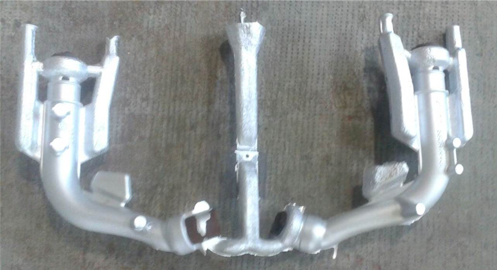
Investigation of Mould Leakages in a Gravity Casting
This article was contributed by Gabriele Taricco of CM Taricco and Stefano Mascetti of XC Engineering.
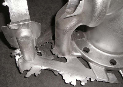
Mould design is a very complex undertaking that must consider not only fluid dynamics and metal solidification patterns, but problems that may arise from the mould itself and how it reacts to stresses from heat transfer. CM Taricco, a mould maker company based in Italy, recently encountered a problem of metal leakages at the bottom of one of their new moulds. The cause of the mould leakages was initially obscure and only appeared after a few process cycles. It was evident that the problem was critical, since it would compromise the production timeline and dramatically increase the costs to cast the part.
Investigation of an idea
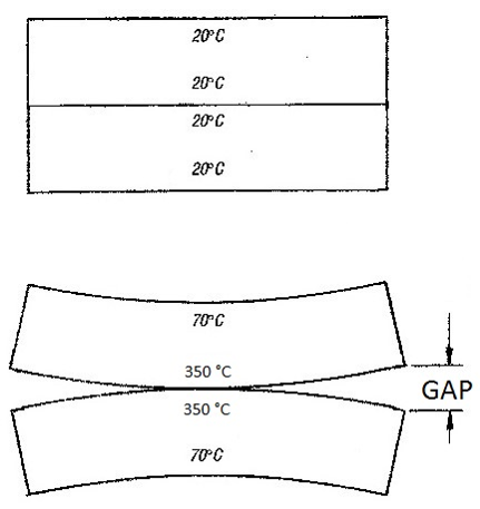
The process itself was a gravity casting, with well-controlled pouring dynamics and overflow designs, so the problem could not come from the fluid dynamics part. The hypothesis of Gabriele Taricco (owner of CM Taricco) was that the metal leakages were resulting from a bad design of the thermal dissipation of the mould, causing a non-uniform distribution of temperature and hence large and unwanted deformations at the bottom of the mould, that were enforced cycle after cycle up to the opening of a critical area where metal could flows out. To verify this and to find a quick solution to the problem, a FLOW-3D simulation was run to exactly visualize what was happening to the mould as it was being heated.
A careful setup, to achieve a fast resolution of the issue
The cause of the problem was to be identified quickly, and an accurate setup – taking advantage of all the most recent FLOW-3D features – was necessary. In particular, the meshing technique adopted was very helpful in order to reduce the number of computational cells to a very low number, keeping almost the same accuracy of a traditional setup, but providing a very fast simulation.
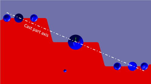
The first trick that was adopted for meshing the mould was to rotate it around the vertical axis in order to align the inner thin cavity of the mould with an orthogonal axis.
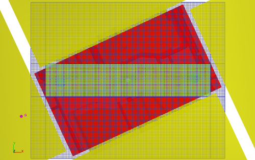
The second trick was to use the new conformal mesh feature for the inner cavity (thin walls), while keeping a traditional larger mesh block for the entire domain. The conformal mesh was conformed to the open volume, and was restricted to the filling cavity only, that had quite small clearances.
A global view of the mould with cores and its alignment with the mesh blocks
Finally, to limit the space externally to the mould (that now became a shoebox shape, rotated 20 degrees, so badly aligned with the model axis), some ‘domain removing’ components were used, defining them directly through the internal solid modeller of FLOW-3D.
The analysis
After a filling simulation, to ensure a good filling pattern, the focus of the simulation was redirected to a thermal die cycling analysis. The setup in this case is fast and straightforward requiring only 1 hour to reproduce 10 production cycles on a common desktop machine (i7 5930K, commercial value 1500 dollars). The result confirmed CM’s initial hypothesis: by looking at the temperature field, from various points of view and cross sections in a single image using FlowSight, it was clear that the temperature distribution of the mould would easily cause the expected deformations and metal leakages.Further analysis with the Fluid-Structure Interaction module
Once the problem was identified and the technical staff could start designing an improved mould, CM Taricco wanted to have a final confirmation running a FEM analysis of stresses and deformations on the die. To perform this analysis, XC Engineering Srl helped CM in setting up and performing the calculation. The result of the analysis showed exactly what CM thought was happening: FLOW-3D was able to reproduce with extreme accuracy the same location and size of the real deformations found on the mould after few pouring cycles. This was good news for CM, and enforces an additional recommendation to use the FSI module at the design stage to predict the real die deformations based on the real casting conditions.Simulation of the mould’s temperature during the die cyclings
Deformation of the mould during the die cyclings, simulated using the Fluid Structure Interaction model. Deformations are amplified x20.
Conclusion
As a conclusion of the analysis, the CM staff was able to design a new optimized mould, using all of the information on the temperature field from the CFD solution. The new mould was able to dissipate the thermal energy in a more efficient way, and the cast pieces were no longer affected by metal leakages even after dozens of process cycles.
Learn more about the versatility and power of modeling metal casting processes with FLOW-3D CAST.
