Mixing different fluids with potentially different properties remains one of the most important and potentially costly industrial processes. In this article, I will complete our presentation of the newly-redesigned particle model in FLOW-3D and take a fresh look into one of the most common and essential industrial processes: mixing.
For most industrial applications, fluids of different surface tension qualities, properties or even rheologies may have to be homogenized in order to continue to the next stage of processing. Mixing can be achieved through different methods, such as impellers, turbulence-causing geometrical structures, oscillations etc., but the desired outcome always remains the same, i.e., achieving a high level of homogenization at the minimum cost. In order to achieve this goal in small-scale industrial applications, a microbubble mixer in which gas particles are injected into a tube can be used to achieve great homogenization between fluids in a relatively small device, as shown in the following example.
Microbubble Mixing Setup
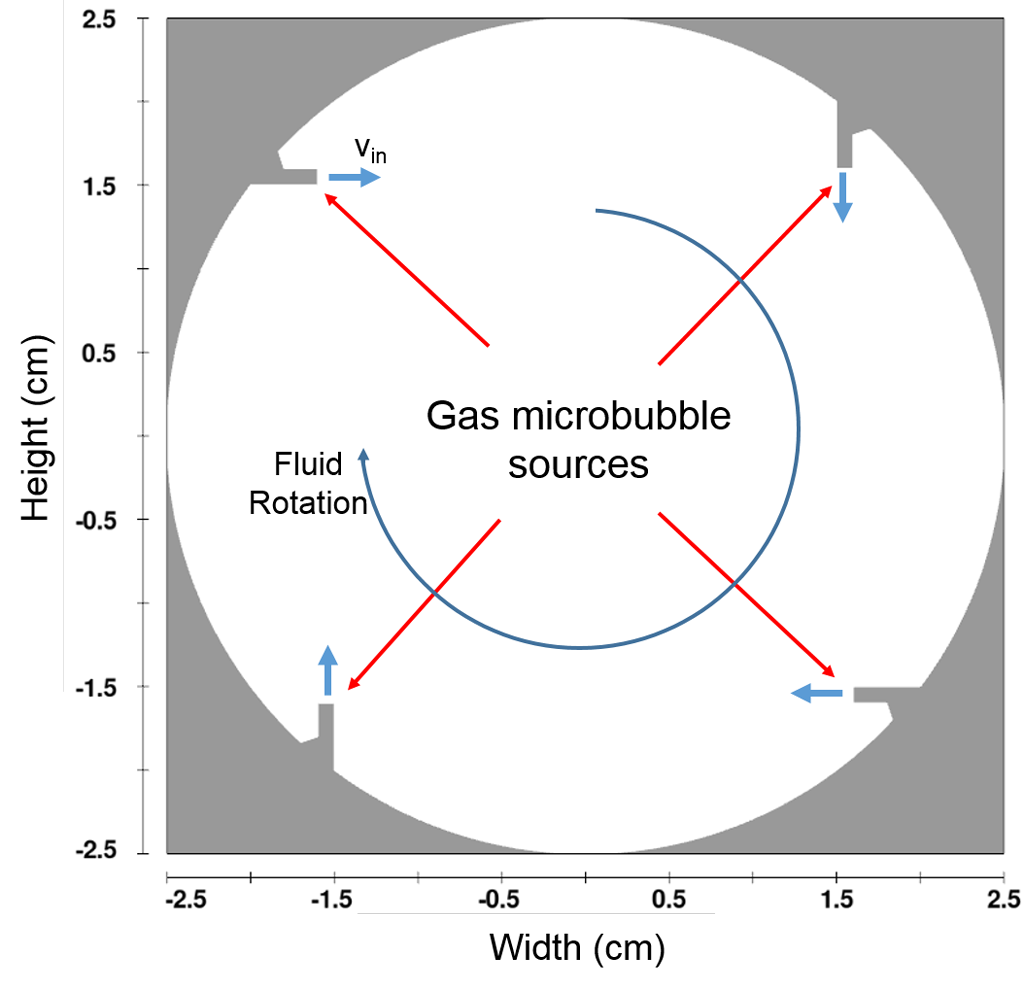
In this case, in order to maintain low cost, I chose to inject CO2 gas microbubbles into a steel tube through 4 inlets, located off-center at each side and protruding into the tube by approximately 3 mm, as shown in the figure below. Carbon dioxide was chosen since it represents a low-cost, chemically-inert gas with stable properties that can be found as a byproduct of various industrial processes, such as combustion, and is easily available in many facilities. For the purpose of this example, the total diameter of the tube was limited to 5 cm and its overall length was set to 20 cm. The inlet velocity was determined to be 1 cm/s. Due to the simplicity of the design, the device can be universally incorporated into a variety of processes.
Initially, the fluid is at rest and an arbitrary concentration of a substance to be mixed is specified only at one half of the cylinder. The boundary conditions were designed to inject fluid at the same concentration profile in order to deliver a completely unmixed fluid at the inlet. Hence, all mixing occurs inside the proposed device.
Role of Gas Particles
Given that no other rotational flow components exist, mixing only occurs due to the injection of carbon dioxide microbubbles modeled as gas particles. The gas particles are injected into the fluid mixture at a velocity of 200 cm/s but quickly slow down because of fluid drag. Since coupled two-way particle-fluid interactions can now be easily modeled, the gas microbubbles affect the flow profile and, due to their initial source placement, generate a turbulent rotational flow. This rotational flow, in conjunction with the geometrical features of the device, acts to quickly and efficiently homogenize the unmixed incoming fluid. Turbulence is modeled with the two equation κ-ω model.
Results
As shown in the animation below, the device performance can be qualitatively evaluated based on the mixing fluid profile at different cross-sections. It can be observed that once steady state conditions have been achieved, fluid mixing improves along the total length of the device.
This animation shows the mixing progress in both time and space. Initially, the fluid is unmixed throughout the domain. At the onset of microbubble injection, a rotational flow is being generated. As shown in the 3 inset plots, mixing quality improves along the length of the device.
In this example simulation, we can readily appreciate the power of FLOW-3D’s new and improved particle model in the case of a gas microbubble mixing simulation. By employing particles, it is easy to design and evaluate the proposed mixer design, which provides exceptional homogenization performance (without any chemicals such as emulsifiers). And this can be achieved at a low cost, since it is completely maintenance-free (no moving parts).
This article concludes my series on the new particle model in FLOW-3D, but certainly we will continue to see plenty of applications where particles are involved. In fact, the three blogs on mass, fluid and gas particles do not completely do justice in covering the scope of how the particle model can be used. Other particle classes like marker, void, probe and user-defined, will have applications in many industries. As a closing remark for the series, I can say that the updated particle model in FLOW-3D has been a significant addition to our solver, and I hope that users will find this new powerful model useful in their modeling work.
In the next blog, I will move on to the updated mooring lines model in FLOW-3D.


