Fish Ladder Design
This article was contributed by Jason Duguay of Université de Sherbrooke (Sherbrooke, Québec)
Barriers to fish migration resulting from perched culverts are an unfortunate reality of the extensive road networks that span North America. Perched culverts result from a combination of improper culvert installation techniques and sediment scour. At the culvert outlet, erosive processes can cause an excessively large scour hole to develop, resulting in a vertical drop between the culvert invert and the downstream water surface varying anywhere between a few centimeters to several meters. Vertical barriers are known to have an important influence on the distribution of fish species in fluvial habitats and are one of the leading causes of small waterway habitat fragmentation.
In this study, FLOW-3D played in instrumental role in the design of an innovative fish baffle for use within fish ladders used to regain lost riverine fish habitats by providing passage over the vertical barriers presented by perched culverts. Our civil and environmental customers now use FLOW-3D HYDRO for these types of modeling and analysis. The study was carried out at the Université de Sherbrooke’s Civil Engineering Department in Québec, Canada. FLOW-3D HYDRO was used to investigate numerous parameters of the flow over the baffles and throughout the pools of the fish ladder to glean insights on how the baffle design may be improved to promote fish passage.
Baffle Design and Fish Passage Criteria
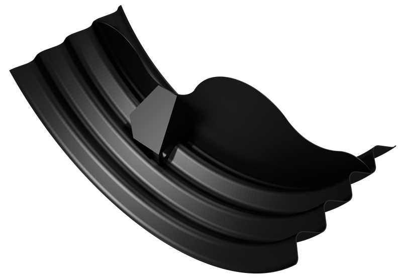
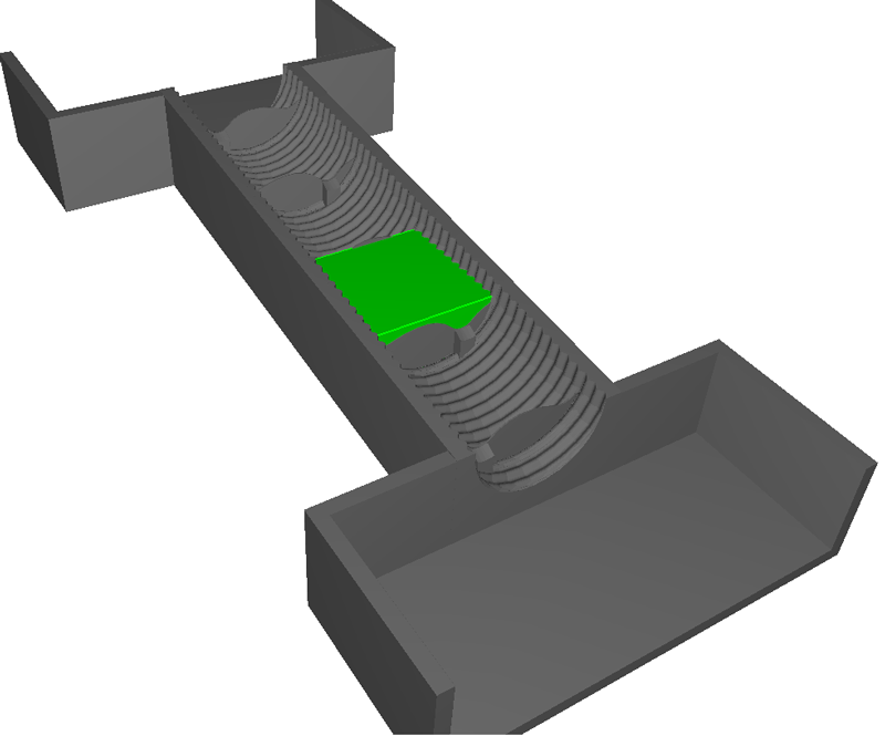
The baffle design has been aptly named the arch baffle*, in reference to its geometric form presented in Figure 1. The baffle consists of an upper and lower passageway to provide for fish passage at high and low flows. A key design feature is that if one passageway becomes blocked due to debris snags, then the other is intended to provide an alternative route for fish passage. The large primary passageway of each baffle is staggered in relation to the preceding baffle (see Figure 2) to reduce velocities and develop large low turbulence recirculation resting zones throughout the ladder.
The protruding arch of the baffle is intended to retain water and increase the depth of the pools at elevated flow rates. Greater pool depths reduce the volumetric dissipative power (VDP) of the pool as calculated with Equation 1, where is density, gravitational constant,
is the flow rate,
is the volume of fluid in the pool, and
is the elevation difference between the water surface of the adjacent upstream pool and the pool in question.
(1)
VDP is a commonly assessed criteria for the design of fish ladders. Larnier et al. 1994 recommend values between 150 W/m3 and 200 W/m3 for applications targeting trout and salmon species common to North America. The complex geometries of the pools and the dependence of on the flow rate through the fish ladder makes VDP difficult to calculate without further insights into how
varies as a function of Q. FLOW-3D HYDRO’s sampling volume functionality proved especially useful for measuring the volume contained within the pool for use in Eq 1. The sampling volume was placed in pool three near the downstream end of the culvert and is visible in Figure 2 as the lime green rectangular box.
The fish ladder design was also verified for velocity and turbulence distributions at the passageways of the arch baffle and within the pools. Elevated velocities impede fish locomotion, and zones of high turbulence disorientate and subject fish to unpredictable and rapidly varying body forces which can affect their ability to navigate flows and successfully ascend the ladder.
The work required to traverse a given distance of ground is proportionate to the cube of the fish speed relative to the ground plus the average velocity of the flow surrounding the fish. Therefore, velocities are sought to be minimized in fish passage designs to reduce the energy output required of the fish, and improve its overall chances of successful passage. Often designs are evaluated for the presence of velocities in excess of the burst (or critical) swim speed of a given target species. The burst speed of a fish can generally only be maintained over an exerting period of a few seconds and recuperation is required before ascent can recommence. Burst speeds of a number of socially and economically important fish species in North America are presented in Figure 3.
Simulation Parameters
The fish ladder design, equipped with the arch baffle, was simulated at two slopes (8.5% and 10 %) and two flow rates (low Q=0.062 m3/s and Q=0.150 m3/s. The two equation k– turbulence model was applied to obtain spatial distributions of turbulent kinetic energy (TKE). The baffles were simulated in a half round corrugated steel culvert ( with 64 mm corrugation depths with a crest to crest distance of 0.230 m. Five baffles were placed in the 10 m long fish ladder and spaced appropriately from each other to obtain a of 0.2 m between pools.
Hardware Information
Simulations were run on an Xeon E5-1650 3.2 GHz 6 core workstation processor with 64 GB of RAM. The total cell count in the domain was roughly 2.5 million cells (with a 0.025 m cell size) and took approximately 5 hrs to simulate 20 seconds of flow.
Results and Discussion
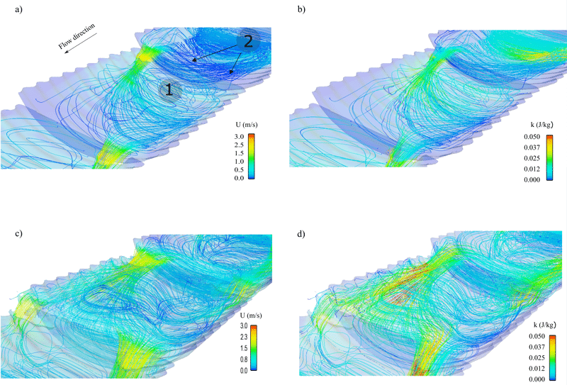
After steady-state conditions were obtained, the results were imported into Flowsight for post-processing and flow field visualization. Spatial distributions of both velocity and turbulence were evaluated along colored streamlines seeded at the upstream end of the fish ladder. An example image of the distribution of velocity magnitude is given in Figure 4a and 4c (low flow, 0.062 m3/s and high flow rates 0.150 m3/s, respectively), alongside the spatial distribution of TKE in Figure 4b and 4d (low flow and high flow respectively).

Comparing the velocity magnitudes in Figure 4a and 4c with those presented in Fig. 3, the fish ladder will likely not pose a velocity barrier to the majority of the adult fish species presented at the flow rates tested. A closer look at Figures 4a and 4b, reveals a large recirculation zone (label 1) characterized by low velocities and low TKE values (relative to the maximum TKE observed in the pool of approximately 0.045 J/kg) immediately downstream of the arch baffle. The location of this recirculation zone is believed to be ideally suited for resting and staging upstream jump attempts through either of the primary or secondary passageways. Another persistent low velocity, low turbulence resting zone was found to occupy the volume on the immediate upstream side of the arch baffle (label 2 in Figure 4a). This zone will likely present fish with a low velocity zone to recuperate and reorientate themselves as they swim through or jump over the higher velocity passageways.
At the high flow rate, results showed that the protruding arch fulfilled its intended function of increasing the pool volume and maintaining VDP to acceptable levels. To illustrate, a VDP of 60 W/m3 was observed for the Q = 0.062 m3/s simulation compared to 117 m3/s for = 0.150 m3/s. VDP increased by only 95%, despite a 140% increase in flow rate, a design feature beneficial for reducing the bulk turbulence within the pools.
Conclusion
Overall, FLOW-3D HYDRO proved to be a flexible tool to rapidly evaluate the influence of a number of baffle design iterations on the flow field of the fish ladder. FLOW-3D HYDRO‘s FAVORize function allowed baffle geometries to be modified and quickly interchanged within the existing model without resorting to extensive remeshing or remodeling the simulations. The results of this study show that the arch baffle and accompanying fish ladder design presents numerous potential benefits to improve fish passage at perched culverts. In the near future, the arch baffle will be tested in a fish passage application similar to the one discussed herein at a culvert in Ontario, Canada which has been blocked to fish passage for a number of decades.
*The idea for the double passageway arch baffle form is credited to Ken Hannaford, biologist with the Newfoundland Government, Canada.
References
Bell, M. C. (1990). Fisheries Handbook of Engineering Requirements and Biological Criteria. U.S. Army Corps of Engineers, 3rd edition.
Larinier, M., Porcher, J., Travade, F., and Gosset, C. (1994). Passes a` poissons -Expertises et conception des ouvrages de franchissement. Conseil Supe´rior de la peˆche.


