This article was contributed by Herman Wijshoff, Océ Technologies
Developing a new inkjet printhead technology is challenging because the extremely high speed and tiny size of these microelectromechanical systems (MEMS) make them very difficult to measure or observe. Océ Technologies has met this challenge by using a combination of several different computer simulation technologies to understand how inkjet design parameters affect printhead performance.
For the computational fluid dynamics work, Océ used FLOW-3D to predict the free-surface flow with surface tension and wall flexibility. Simulations enable Océ engineers to quickly evaluate the performance of a wide range of possible designs and zero in on the most promising alternatives into which substantial time and expense required for MEMS prototyping is invested. Using CFD simulation to confirm and improve their inkjet printhead performance, Océ was recently able to develop new wide-format printers delivering a printing speed much faster than the current generation of printers.
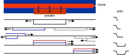
An electric voltage on a piezo element enlarges the channel and a negative pressure is generated. After reflection at the reservoir this pressure is amplified by the second slope of the driving waveform to get a large positive pressure peak at the nozzle, which fires a drop.An inkjet printhead contains many long channels with a nozzle at one end and an ink reservoir at the other end. A piezo actuator element provides the driving force by enlarging and contracting the channel which produces pressure waves. To initiate the firing cycle, the actuator first enlarges the channel cross-section, producing a negative pressure wave that is reflected at the reservoir. In the second step, the driving voltage is turned off, thus reducing the channel cross-section to its original size and amplifying the reflected positive pressure wave, which fires a drop. The head of the drop drags a long tail along. Long tails are formed when the head of the drop has a higher speed than the tail and the tail breaks up into satellite droplets. After the drop is fired, the channel is refilled with ink.
The Challenge of Doubling Printhead Speed
Océ’s goal in designing the new printhead was to increase speed by at least a factor of two while maintaining print quality and reliability at levels equal to or better than the high standards of the previous generation of printheads. They also wanted to keep driving voltages low to reduce power consumption and the cost of the electronics. Doubling the speed of the printhead meant increasing the frequency of the driving electronics to several tens of kHz. In order to maintain print quality at this speed, it was necessary to maintain a high drop speed. Drop speed is usually limited by the tail because if the tail gets too long it will break up into satellite drops which will adversely affect quality. So, one of the key factors in increasing the speed of the printhead is increasing the tail speed.
Another critical factor in increasing the speed of the printhead is refilling the printer at a faster rate without wetting the nozzle to a degree that would affect print quality. In order to fire drops at a very high speed, free-surface flow in the nozzle and acoustics in the channel must be designed to refill the nozzle very quickly. However, this creates a tendency for the nozzle to overfill which can cause wetting of the nozzle plate. A wet nozzle can affect drop formation depending on the thickness of the wet layer and the size of the drop. For example, 5 micron wetting will not be a problem with a 50 micron droplet but will have a major effect on a 10 micron droplet.
Build and Test vs. Simulation
Earlier generations of inkjet printers were designed by building and testing prototypes. The problem with this approach is that it takes several months to physically build and test a printhead. In addition, it’s very difficult to obtain diagnostic information when testing because of the small size and the high speed at which it operates. Droplets can be observed by optical methods such as stroboscopic illumination but the critical phenomena inside channels are very difficult to measure.
For these reasons, Océ engineers rely heavily on computer simulation to evaluate printhead performance prior to building prototypes. The simulation of printhead operation is complicated by multiple physical mechanisms. FEA modeling is used to understand the deformation of the printhead walls when voltage is applied to the piezo elements, and also to identify complex interactions of the printhead structure dynamics with channel acoustics.
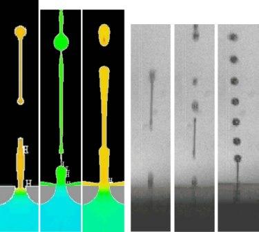
A 2D axi-symmetric FLOW-3D model is used to obtain the details of the drop formation process. This is the most challenging part of the simulation because of the difficulty of modeling free surfaces. Océ engineers previously evaluated all of the leading CFD software programs for their ability to handle this challenging simulation problem. They simulated the printhead using each of the codes and compared the results to physical experiments. For example, they evaluated the ability of each software program to correctly predict the formation of a drop and its secondary tail. FLOW-3D‘s simulation results were very close to Océ’s experimental measurements and were substantially more accurate than the other CFD programs. Océ has been using FLOW-3D for many years and has found that the software continually provides highly accurate results.
Modeling the New Printhead
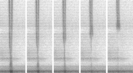
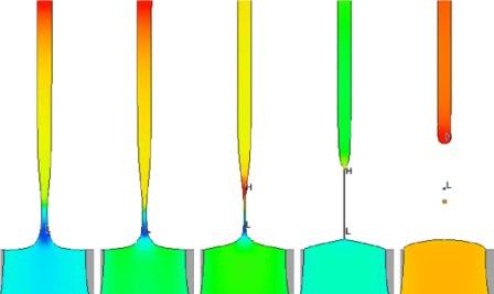
The secondary tail has a width of about 1 micron, which is close to the optical resolution of the measurement setup. The recordings are made using a strobe, so only the reproducible part of the drop formation is shown.Océ engineers also used FLOW-3D to simulate the effects of their design parameters, such as evaluating tail breakup based on such factors as ink viscosity and channel geometry. Simulation allowed them to examine the formation of a secondary tail as a consequence of going through three flow regimes with different dominating forces.
First the tail width decreases slowly with only viscous and surface tension forces present. Then, when the tail starts to break off, inertia, becomes important and the tail width decreases rapidly. Viscous forces play no role when the tail width becomes smaller than the viscous length scale. With two remaining factors, surface tension and inertia, the tail width again decreases slowly. The small secondary tail breaks up into very small droplets, which are dragged along with the airflow induced by the firing sequence of drops.
Simulation Matches Physical Measurements
FLOW-3D provides very accurate predictions of even the finest details of the tail breakup as can be seen by comparing Figures 2 and 3. The accuracy of these predictions makes it possible to determine the effect of varying design parameters on tail breakup with a high degree of precision. FLOW-3D simulations can take several days, but this is much faster than the several months required to build and test a prototype. However, Océ engineers have developed a method that enables them to evaluate the performance of a combination of design variables even more quickly.
They perform multiple simulations with FLOW-3D to determine the sensitivity of various design objectives such as tail speed to design variables such as channel length and nozzle diameter. They use these results to write a MATLAB routine that can provide predictions of the performance of thousands of different combinations of design variables in a single day. When Océ engineers identify a promising new design through the MATLAB routine, they run a more detailed FLOW-3D simulation to verify its performance. Using this approach, they narrowed tens of thousands of possible design combinations down to just a few that provided the combination of high-speed print performance, optimal print quality, high reliability and low manufacturing costs need for the new printhead design.
When Océ engineers built and tested the prototypes they discovered that performance closely matched FLOW-3D’s simulation results. The new printheads will be used in a family of wide-format printers, ranging in width from 42 to 62 inches, that significantly increase the performance in terms of productivity, quality, reliability and running costs. Without using CFD simulations, Océ’s engineers believe this project would have required at least twice as much time using traditional design methods, if it could have been accomplished at all.
Learn more about the power and versatility of modeling inkjet applications with FLOW-3D.


