CFD + Physical Modeling Results
This material was provided by Kevin Sydor, M.Sc., P.Eng., Section Head, Hydrotechnical and Oceanographic Studies, Water Resources Engineering; Manitoba Hydro; Joe Groeneveld, Western Canada Discipline Practice Lead – Hydrotechnical, Hatch Ltd.; Graham Holder, Consultant, LaSalle; D.G. Murray, P.Eng., M.Sc., Discipline Practice Lead – Hydrotechnical, Hatch Ltd.
For over a decade, Manitoba Hydro has tackled the complexity of hydroelectric plant design with the power of FLOW-3D. Our civil and environmental customers now use FLOW-3D HYDRO for these types of modeling and analysis. More recently, Manitoba Hydro has focused efforts on pre-commitment design studies for the proposed Keeyask Generating Station, at a complicated location that includes rapids, multiple channels, and natural contours. Building on previous use of FLOW-3D HYDRO for initial design concepts, the company performed an integrated study where the combined results from both simulations and physical modeling served to validate and improve each other’s performance.
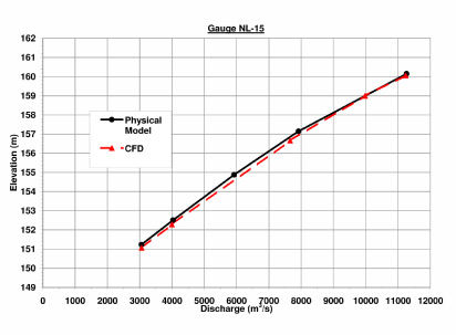
Two phases of river diversion were necessary to create temporary sections of dry land for the actual powerhouse and spillway construction. Manitoba Hydro conducted simulations to estimate how water levels and velocities at various locations would change as physical conditions change during construction of the temporary cofferdams. They then compared results with those measured on a 1/120 scale model of the cofferdam construction, diversion structure, river closure, and spillway, and a 1/50 model of a section of the spillway. Nuances observed in the 1/120 model’s operation led to its modification, whose details were fed back as changes in the STL model representing boundary conditions within the CFD simulations. The detailed back-and-forth process not only predicted the behavior of the physical scale model within approximately 5 percent but also uncovered design changes that would save on construction costs.
Setting up and Calibrating the CFD Model
The CFD model covered an area about 3 km by 2 km, with boundary conditions set by a velocity boundary to control flow into the upstream end and a continuative outflow boundary at the downstream end. The designers imported STL AutoCAD files of geometric objects such as piers, abutments, the spillway structure and the cofferdams to represent physical boundaries then defined the flow parameters.
To accommodate both the characteristics of the river rapids and the expected range of flow rates churning through the parallel sections of the spillway, the CFD model was set up to use a renormalized group turbulent mode and an implicit pressure-velocity solver based on the generalized minimum residual method.
The mesh was set up with Cartesian coordinates and used nested mesh blocks to refine the grid in areas that required finer meshing. Grid spacing in the area around the spillway structure was set at 1m by 1m by 1m, necessary to include the shapes of the spillway piers, abutments, and spillway crest.
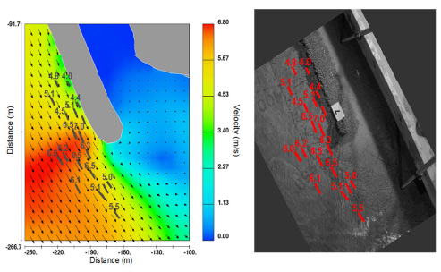
Goals for the simulation included estimating the discharge capacities, water levels, velocities and flow patterns, at various points on the construction timeline, and for different positions of the spillway gates (from partially to completely open). These calculated values are important for choosing the size of stone needed for rockfill during the cofferdam construction. Individual boulders must be large enough to resist the drag forces that work to move them out of place and downstream at all stages of construction.
Physical Modeling
With hydroelectric plant design, too much is at stake not to get it right the first time. Building a scale physical model of critical flow areas is still necessary to verify capacities, pressures, velocities and spillway gate behavior (fully and partially opened) at critical topographic points for different discharge rates. Manitoba Hydro asked the LaSalle Consulting Group to build two such models – one comprehensive layout at 1/120 scale and one partial spillway model with two full-bays and two half-bays at 1/50 scale.

Integrated Modeling Results
The simulations for rock sizing predictions came in slightly conservative when looking at the force/movement relationship of sizes in the physical model. However, initial water-level data curves showed good agreement between the simulation and physical model behavior, setting the stage for further testing. As the cofferdam was slowly constructed in the model, subsequent water-level measurements showed that the CFD simulation accurately predicted the required freeboard under construction design flood conditions.
Physical testing of the completed cofferdam showed that the flow was being controlled at the channel entrance, instead of at the control structure. This resulted in higher upstream water levels than desired. The physical model was reconfigured to lower the entrance of the approach channel, reflecting the elevations used in the CFD model. With the entrance of the channel excavated to a lower level, excavation along the left bank of the channel was only necessary at a smaller area near the entrance.
Conclusion
Manitoba Hydro found that CFD modeling offers multiple benefits for planning the construction and operation of the Keeyask Generating Station as well as future hydroelectric plants. Not only was there very good agreement between the results of the two approaches, but combining the FLOW-3D HYDRO simulations with scale-model testing offered an iterative path to improving the validity of both design options. Further, the simulation let users easily and quickly extract velocity, water level, and flow rates anywhere within the CFD model domain, as opposed to the limited number of values that could practicably be obtained with physical gauges and time-lapse photography.


